Warp-Drive-Physics.com
See: lightdrive-ascension.com
  • Home
  • Warp Drive News
  • Warp Drive Blog
  • Metaphysics Blog
  • Warp Drive Philosophy
  • Warp Drive Engineering
  • Tesla Engineering Physics
  • Construction
  • Construction Blog
  • Updates and Design Improvements
  • Outer Ring
  • Exo-Archaeoastronomy Blog
  • Planetary News
  • Ascension Blog
  • General Blog
  • Free Energy / Tesla
  • Info

Central Accumulator Construction

1/31/2016

44 Comments

 
                                                                                                                                             Updated: 2/9/16

                                 The Spark of Life


​
This is a simple approach, I don't want to get overly complex with this.

As a resolution to the Life Force philosophy concerning a living energy component in the system, the engineering balks at it. The only easy way to do that would not be a permanent way. What is most Sacred is most Permanent. The Central Accumulator should use Power Cell Electrets primarily. For one thing, having a living electrolyte can decay, and that is a much worse energy to be around.

Here is a simple cutaway view to give you an idea.  Regarding an utron however: An utron as a solid component of mass with a conductive non-magnetic surface and non-magnetic core is a better inertial generator. An utron picks up an electric charge in paradox to the motion of the electromagnets. This is required for "electro-gravitation." 

​
Otis said they acted as the "batteries" that revolved around in motion, because he was dealing with a self-regenerating circuitry, not with a Central Accumulator as a permanent battery that never dies out.


However, using a Living Electrolyte, with alternating copper and zinc plates, the zinc would be consumed in the energy reaction, and I am unsure if self-re-energizing the battery would prevent that, but with a Spark Gap inside, it would become a Living Energy Battery.


​
There would be more power overall, would require the Accumulator to be separated into halves, and the Bedini Schoolgirl circuit would be the circuit that works. There are some interesting things about Utrons regarding their electrical capabilities when moved through electromagnetic field coils as the OTC-X1 Engineer teams have discovered. Also Carr said that the Utrons act as COILS (Bedini! Hint Hint).

Separating into halves is an easy thing, separated and affixed to the central rotating disk (accumulator frame), where the appropriate electric connections can be made (conductive strips and electrodes). The interior sphere can adjoin in nearly halves, where the accumulator frame (central disk) can make up that difference at the equator. It doesn't have to be a perfect, but the spark gap should be attempted PARTICULARLY when it is surrounded by a living energy eletrolyte such as fresh leaves and brown sugar mixed to a paste.

​Actually, I wouldn't use sugar AT ALL.  That does have destructive properties to the body's aura, which has been shown through science. I would use something different, if I were you.

A Living Electrolyte Energy would feel very good, I imagine, to those who have spent years living in Tesla fields!

THAT aspect of a Living Energy Battery is more worthy to build then a Power Cell Elecret Accumulator, and could be Life-Saving and Life-Regenerating. I would be a fool to just summarily discount that.  Luckily, the wiring should not be all that different as described below, which all mainly pertains to a Power Cell Electret Accumulator, just to make things more interesting.  

The design of the Accumulator "Reactor" below will not change, other than the plate material, and whatever considerations for dealing with the electrolyte without it seeping into the hollow sphere. You'll have the benefit of seeing two designs in one, somewhat at the same time (multidimensional article), and in somewhat of a comparison / contrast. 


​
​
​
It won't spark itself. It has to be sparked by a high volt flyback charge from the apparatus it's connected into.

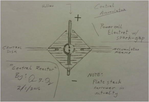
Here is a quick view just to give you an idea:
Picture
By the way, this design is used with the living electrolyte as a battery with zinc and copper plates. This configuration can be used as a capacitor, but it would require some voltage. Using an electret however, the plates can be stacked just like a capacitor, all in the same polarity positive on the top of each plate, and negative on the bottom of each plate for a DC charge; battery. That later configuration also allows for an external charge to be applied to the central accumulator, and the energy self-organize or otherwise polarize without resisting itself. ... Also an electret power cell would never die, it would be permanent instead of temporary (definition of electret). ... The purpose of the alternating plate stack is for an electrolyte battery, even though such a design is used in capacitors, essentially. But now that negative energy is better understood, a power cell electret would work just fine instead of limiting it to using a living electrolyte only. Interesting to note the similarity between battery and capacitor designs. Electrolyte capacitors and batteries aren't that much different, apparently. (1/1/17)


​We can even commutate it or use a Bedini schoolgirl circuit to get the spark in the correct polarity!


If I may make a note on materials of the Central Accumulator. Mixing copper and aluminum will cause corrosion because they react together to create a small current. Eventually the aluminum will be consumed.


                     I have noticed some flaws in the design above. The bottom electrode has
                     to run up in an insulated passage to the gap inside, and a wider rim must
                     be present in the hollow cavity so the spark arcs where one intends it to be
​                     arced (won't arc off the frame).

                     Hah!  Even better. Do away with the top spark gap electrode in the center
                     of the Central Accumulator, and just run the lower electrode to the direct 
                     center of the inside sphere, like a plasma globe. It would resemble the radius
                     of the sphere, half the diameter in relation to half the circumference, but as 
​                     the PI of a sphere, where the Origin is a point of charge.


  --->   In parallel, volts don't add, amps do.  The Accumulator internal structure is stacked in plates, so it could get up to some voltage (not a whole lot, but maybe 20 to 30 for a small test model). It would be easy to see how many watts an accumulator would generate and the breakdown of volts / amps. Easy enough to design a scale model, and add up the output per each segment. Would be making a bit of a guess, but it could be a close estimate. 

I think a Hutchison power cell matrix would just be a whole lot easier overall, also (UPDATE! NO! A LIVING ENERGY BATTERY IS BETTER! ALL THE BELOW MAY NOT HAVE SUCH UPDATE NOTIFICATIONS). We'd be using the whole accumulator instead of halves. It would last forever. Using rubber o-rings to divide each plate stage into segments would make more efficient use of that Power Cell compound since it doesn't produce a whole lot of power. A Central Accumulator of this design can include a hollow space in the middle.

Easy to build.

You can't just do this though: Fill with compound, add a plate. Next segment:  Put rubber spacers in, fill with compound, add a plate, repeat. Charge. Hold. Let it cure. 

The reason why is because each segment must be charged separately, because each segment won't generate but maybe .8 volts.  So the volts would have to stack, so they add up; and in parallel the amps can add up in the wider parts of the Accumulator, using multiple rubber o-ring spacers to create segments that can be connected in parallel and in series, to add up amps and volts.

Each power cell electret shape can be molded into the appropriate shapes and have them pre-charged up. So we just drop it right into the Central Accumulator assembly as we assemble each half.

..............................


Benefits:  

               last forever (or for a long time, 20 years?  Dunno about that part)

               It would simplify the wiring of the OTC-X1 (except for the commutator)

               Would not require a commutator (actually, it just might after all; see below)

               We could easily pulse the current (start and stop it) in the outer electromagnets to obtain field
               collapses if we so desire.


Dr. Ning Li of the Huntsville NASA facility was working on a gravity engine using a Bose-Einstein ionic condensate where the charges of the particles were all in alignment, and she rotated a magnetic field over it. She used lasers to stimulate the condensate so the particles spun at a high rate. She ended up seeking funding to further its construction, and ended up leaving NASA and working for the Chinese government. Haven't heard about her since, really.

www.warpmetrics.com   ...   they also discuss an alignment of charge in a rotating magnetic field.


That's what's happening in the OTC-X1 with the charged utrons, and the rotating magnetic field of the outer "rake" of c-shaped electromagnets.

But whereas Dr. Ning Li was trying to harness the entire mass of the charged particles in condensate, we are already harnessing a significant mass with the spinning gyroscopic action of the utrons. Now this is relative!  The weight never changes, but we have an inertial force generated gyroscopically.


EAGLEWORKS-NASA is also wanting to work with a condensate. 


PART II

I really want to make sure that this simple concept is known:


When an electromagnetic field collapses, it does so at the "speed of light," at in resonance with the whole coil and all the strands of wires. That field collapse creates a back voltage due to the motion of the field as it collapses rapidly through a field coil.  That also creates a very high volt spark if harnessed in a spark gap. That single discharge is what is harnessed to recharge the batteries in a self-regenerating circuit, such as a Bedini schoolgirl circuit.

That same thing happens in an induction coil that generates a spark. That's how it works. (This is for the OTC-X1 Engineer who commented)

Strangely enough, generating an electromagnetic field does not do anything out of the ordinary. A magnetic field collapse also multiplies upon itself in resonance (like how a bar antenna which is a coil of wire must use a magnet in the center to increase its frequency of what radio stations it can receive).

A forceful reversal of a magnetic field collapse, driving another magnetic field in opposite polarity will push a more forceful high volt spark.  That is called a "snap reversal."

Such a reversal could be achieved at the "top dead center" point of the utron.

​I want to make sure that these dynamics are also understood.

This is also another example of "magnetic field compression" or "condensing" the magnetic field.
​


Theory:


Let's examine the Central Accumulator shape.  Volts stack. Amps are strongest at the width.

What we have is a "lattice."      This is also true for the Living Energy Electrolyte Accumulator design. 

At the widest edges of the Central Accumulator, the volts stack vertically. The wider plate-stacks will carry the highest volts. That volts stack all the way to the narrow widths of the tips of the Central Accumulator.

What will Amps do?

We can't add each segment up to gain higher amps, because that addition is reserved for voltage only; but that does not mean that the amp-rating for the Central Accumulator is only obtained at the little electrets near the tips, because that discounts all the other amps.

Electricity will also travel along the inside edges of the Central Accumulator housing, which are conical at a 45 degree angle, so half the amps from a horizontal section will add. Where's the other half? How does that affect or transform voltage?

​
I think the plate stack will also develop some resonance; the difference between a capacitor and a battery is that the battery is self-generating.


This is also why the Central Accumulator has to be much larger in comparison to the outer electromagnets, and the utrons.


A hollow spot can be constructed so when the two Accumulator halves are screwed together, it leaves a hollow sphere in the center, but we don't want to isolate that place in a faraday cage. We want to allow the "guts of the plate stacks" to poke through a bit, maybe using an electrode flush with the inner hollow sphere, but with a little air-gap around the electrode to the inner housing.

That hollow spot will accumulate a charge; but, it may be different than what we're used to, conventionally. A zero pole of a magnet does exist, and you can track it with a piece of magnetic reading paper. There's nothing much going on at the zero, other than inner-folding action of energy upon itself. We could extend a couple of electrodes in that area though, give it some light to see what's going on.

But the electrodes will be charged, and by allowing energy to form in the center, it becomes more dynamic. (see the above diagram).  Magneto-Electrostatic Current.

​Any time a spark gap is used on a circuit, then that energy primarily becomes magneto-electrostatic; it literally changes the entire nature of the whole system in the most totally remarkable way!

A self-regenerating Bedini circuit will use high volt flyback from the collapse of a magnetic field to recharge the battery. That can be harnessed through a single spark gap as magneto-electrostatic current. However since this battery does not need to be recharged as a power-cell-electret, it would still accumulate a charge from the "spark-space" in the center of the Central Accumulator-Reactor. It has the potential to overcharge.

The spark is easiy to obtain in a Bedini self-regenerative setup, such as what the Living Energy Reactor will do. Just because it has a spark gap to jump, it will still recharge the battery and provide an "over-volt" static charge.


The only theory involving the hollow sphere so far, is involving the "light space" in the middle, for the reason that in a high enough gravity field, that space will not interact very well due to too much of a time dilation involved. The energy of that time dilation can harness a charge, however. 


​


PART III  

steering, maneuvering, pilot interface


These are the next to be addressed, which are still being reverse-engineered.  

Steering may be accomplished by adjustment of the field coils.  360 degrees in a circle.  At 0 degrees, or at 90 degrees, the electromagnets could turn off (or be weakened) in that quarter of an area, and in timing. That would adjust the voltage applied to the utrons, and the ship would drop a little there.

That energy would go toward the rest of the electromagnets, giving 'er a push!

Increasing the voltage to the utrons over an arc at the front of the ship while decreasing the voltage toward the rear arc could pitch the ship up. The ship could roll to the left or right similarly.

Knowing how it works makes it a lot easier to know how to fly it. John Searle's crafts flew in a similar manner.


In an advanced version, rotating electrogravity hull plating can be used using principles of Townsend Brown, to move it laterally in a direction, or adjust the trim.  Searle's craft developed a charge on the surface of the skin. A plunger rod would stop that area from developing a charge for an easy way to pilot his style of craft.

The large picture on the home page has a graphic representation of this on the right side about mid-way.

Searle used just a simple form of maneuvering just from a basic hull, merely charged. Positive charge toward the front and negative toward the back will move a ship forward. Adjusting the charge along the wing-tip edges to turn them on or off was Searle's method. Charged hull surface developed naturally due to the rotating magnets of his engine.


​

A spark discharge however, could be applied to steer the craft, in a collapse or field reversal of an outer electromagnet. As it might suddenly reverse the charge of one utron for an instant, it could affect the motion of the craft. 


​ 

Thought-piloting the craft would require a photonic interface. Brainwaves emit photons. Photons are magneto-electrostatic waves.  There was an easy way to achieve that in the recent past, and so it is an easy thing that will eventually come along. Just as I experienced through my own Tesla electrostatic field, it can also apply in an engine!

Now here is where a living energy battery system might have a serious impact to be compatible with a thought / intention Pilot interface. Chances are it would not work without a living energy component to the Central Accumulator.


It's interesting though that there is a "light space" in the Central Accumulator. I wonder if it will change color per frequency? This would change the entire design of the Central Accumulator, separating the two halves and adjoining them to the central rotating disk frame. 

Information (light) of the engine frequencies would have to be known from outside the Central Accumulator. So there must be a design that can incorporate this, so the two halves of the Central Accumulator can be screwed onto the central rotating disk.


A spark gap can be included inside the Central Accumulator.

It can also be a particular bridge. The electrodes of the Central Accumulator can extend also to this region of the internal hollow cavity.  It is something to consider. Perhaps Argon gas fills the space, as Tesla was so fond of. A hollow tube going up the drive shaft could be fitted with a crystal globe device, all air tight using pressure bearings if need be. The crystal sphere or globe device might require an electrostatic fractal array inside. See toward the bottom of the Warp Drive News page. 

Radiant Rise:  That is an electrostatic current that flows out toward air, say from ground.  You always put your bare coils, plates, spheres, toroids up away from ground, and openly exposed to air.  We've got a ground with the spark gap, and an "open air" with a crystal sphere, even though it may be filled with something like argon gas. Glass will conduct an electrostatic charge also out into the surrounding air of the cockpit.


This applies to the Electret aspect:

If sparks are created right over the utrons, from quickly turning off and on the electromagnets in rotations in a point-style timing around a flywheel type of design, then the collapse of the electromagnet would ultimately spark between the gaps inside the Central Accumulator.


Energy coming from the utrons may not need to be harnessed but only within itself, very likely boosting the output tremendously, of the electro-inertial  field shape.         Electro-Gravity


Flyback through the electromagnets' own circuit would create a spark, if gapped in the central accumulator.  See the mini-section below about "Wiring the Spark Gap."

​
That perhaps is the easiest way to achieve it. Just merely extend the electrodes of the Central Accumulator close to each other for its own spark gap.  We can even use a comutator.  

Although with a Hutchison Power Cell Electret usage, it probably wouldn't matter. The only time polarity seems to matter as far as a spark goes is just how a secondary coil is connected after the spark gap down the line. One polarity or the other, it will place more electrostatic energy on either the floor or a ceiling, in a Tesla transformer setup.


The interesting thing about this, though.  Let's say there can be a system-wide spark gap at the center of the Central accumulator, in the inner hollow space.

That would be a more direct way of CHARGING the battery!  This would be very fun to play with.


It would charge the Accumulator Spherical Center with a static scalar space. That would turn the entire nature of the overall energy into magneto-electrostatic.


​Corey Goode, a Secret Space Program whistle blower mentioned two things in a sentence once pertaining to what is required for a basic warp drive:  Gravity Cancellation, and a Static Electromagnet.

     --- >     The Force of Inertia transmitted through a Scalar Field.


WIRING THE SPARK GAP:


This requires a type of Bedini schoolgirl setup.  The utrons acts as coils. See the Bedini schoolgirl circuit schematic on the Warp Drive Engineering page.

This would require the utrons to be connected into the circuit.  When the electromagnets collapse their field (turned off), that energy has to run back to the Central Accumulator.  Historically the OTC-X1 used a self-regenerating circuit. But since it is using a power cell eletret in this design, the battery doesn't need to be re-charged, but we can treat it the same.

It occurs to me, if the electromagnets are turned off, and the circuit is broken, then flyback volts won't return to the Central Accumulator, but must go elsewhere instead.  The most logical place is to the utron. A connection by wire to the commutator (see below) would momentarily connect the circuit to the Central "Reactor" for current to flow. 


An Example of sparking:

If the power to the electromagnets are shut off like with a commutator function, but using a special type of switch that just barely breaks the contact, then as the electromagnet field collapses, a spark will jump that gap, and travel back to the Central Accumulator spark gap.

We know that the crystal globe in the cockpit changed colors denoting the electrical frequencies of the engine. So that must be included into the engine design however, and so it would involve the utrons, or something that involves a change of frequency (motion, increasing distance -- speed -- between timing points, and the like). 


The historic OTC-X1 craft used a self-regenerative circuit, probably the very same circuit used by John Bedini as seen on the warp drive engineering page. Central Accumulator in two separate halves, or otherwise separated by an "accretion disk" with electrodes / contact points. *

One could get creative with the circuit design of a permanent battery, though.


NEW INFO:  Check out the Video of how to understand a Bedini circuit on the post just below this one, or just click here and scroll to the end of the article:   http://www.warp-drive-physics.com/construction-blog/otc-x1-reverse-engineering-breakthrough


​

​


COMMUTATION:  
​
           --- >   I want to briefly touch on this.  There are a number of ways to do this.  There is a handy space between the Central Accumulator, and the capacitor plates, and that's the only space we have to work with.

Since wires have to be run to the capacitor plates from the Accumulator (the "Reactor"), then there is a place to lay down some metal contact strips along the circuit route.   Very stiff rods can reach, affixed to the electromagnet-support frames close toward the center of the craft, and they can have a rolling ball or metal wheel that rolls along, making contact with the conductive plates, and rolling along, also contacting non-conductive Accumulator framing.  It would be better than a brush. Tension can be applied with a spring. It wouldn't wear down any parts.

There is enough space on the original OTC-X1 blueprint to allow contact plates to be positioned far enough apart, on both top and bottom of the Central Rotating Disk Frame affixed to the Central Accumulator "Reactor."  They should be far enough apart so no spark will arc across any contact plate. There can be strips further in toward the center, and further out toward the electromagnets, in that "commutating area space" to make sure there is enough space so no sparks will arc needlessly, and cutting power to the electromagnets, shorting across connecting strips.

I've made similar commutators. You just cross the wires over to the opposite ends and reverse the polarity when the current is supposed to be in the opposite polarity of what you'd connect directly to otherwise.

Pretty neat!  Utrons also act as coils, so there is plenty of interaction available for a reactive and resonating "spark"  magneto-electrostatic  circuitry. Since the utrons act not only as inertial generators (solid construction), but also coils, then there very well may be a zero point at top dead center over the utrons, at a magnetic gate or "zero" axis of symmetry.  


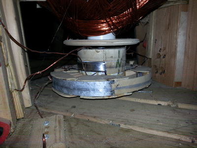
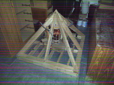
I would think some sort of additional frame (a wiring platform) would mount to the outer frame and/or inner frame, could even use bearings, to handle all the transmissions of the energy, placed in the space that you can clearly see just right around the Central Accumulator in the image on the next post below. Such a thing could be creatively done.


​
                                                ~.~.~.~.|.~.~.~.~


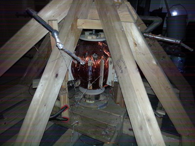
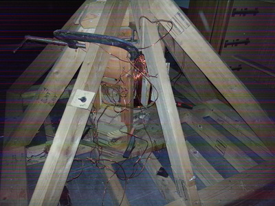
The images below are an experimental generator / motor I built using two outer coils and then the one large one you see. The outer coils poked inside the big coil, and there is a very large magnet inside. I was experimenting with perpetual energy before I discovered the Bedini School-Girl circuit.

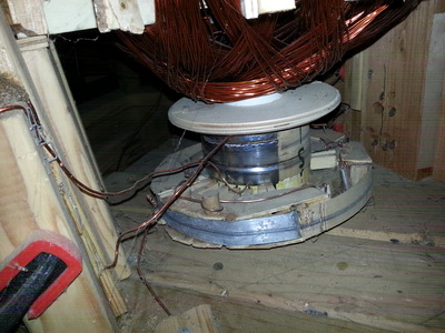
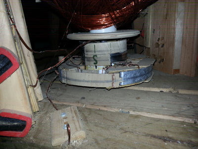
Notice the little round thing at the bottom though. That is the Commutator. 

It could either generate AC, or DC, and it could be powered by a car battery (12 volt DC) and generate AC, OR DC.  The commutator made all that possible. 


This is to satisfy the OTC-X1 Engineer in the comments who wanted more substance behind my words.​ Thank you, OTC-X1 Engineer for giving me the perfect moment to share this bit about Commutation; from one engineer to another:
Above:  various photos of the generator / motor, itself.

​Below:  Photos of the Commutator! 
These above are photos of the Commutator. It used 6 wires primarily that could be connected (touching the contact plates). It was a very simple thing to figure out. 

The wider disk at the bottom, I could have put that shiny metal conductive plate instead of around the outer edge, but on top of the flat part of the wheel, like how the OTC-X1 commutator can be. There is so much space on the flat central rotating disk (accumulator frame) right beside the Central Accumulator. 

The photos above are rough and crude, but the OTC-X1 engine would have to be much more refined than this.   The purpose of a commutator is to switch the polarities around so you can get an AC current going in DC. That's it.  That's basically its purpose. Naturally, a magnet and a coil of wire generates only in AC. So it's easy to get it to generate an AC current. But, it has to be commutated to generate a DC current.  

In a DC generator though (there are several ways to generate pure DC; I've experimented with all of that), sometimes you're going to want AC. You do it exactly the same way, the polarities are reversed at intervals in degrees around a circle. If you want to switch the connections, you have a standard connection (common terminal) of 2 wires, and then you have 4 wires coming in for both polarities of DC current (to alternate). You could just rapidly switch the wires back and forth, criss-crossing and un-crossing, but why do that when we can rotate a wheel, to do it automatically while the wires just stay where they are?

That's the concept. An easy way would be to use your 4 wires, call it "Circuit #1" and "Circuit #2" and have the wires positioned on the wheel in (+,-) and (-,+) polarities.  As the wheel turns, you time it by making those wires touch a conductive plate that goes to your common circuit, and then it alternates. It's easy to do. You can either run your common circuit with 4 wires instead of 2.  That's probably the most lame way to do it (with 4 wires going to the commutator as the common circuit instead of just 2), but it's not that difficult of a thing to do is my point.

Look VERY closely at it ...   you can click on the pictures and zoom in.  I screwed up and had to use a dremel to cut the wide plate so I could have an extra "electrical-contact pole" on top. It was one of those "Doh!" moments. 


Path of Current:

One thing I learned with this, is that electromagnetic current does indeed take the shortest path (I had to try it).  However, electrostatic fields and current are not limited to that. For example, an electromagnetic current can take a winding path along a bare wire around a squirrel cage. If there is bare wire touching metal framing, that current will take the shortest path.  You don't have to worry with that limitation using electrostatic current. 

Another thing with electromagnetic current used on a bare-wire winding around a squirrel cage, is that an electric field will run in parallel. It does not run around in a spiral, but takes a path from the top of the squirrel cage straight down to the bottom (along z-axis, the height of a cylinder)!  Eric Dollard and his genius Ham Radio Operator friends clocked the electrostatic wave (parallel wave) at 220,000 miles per second!  

​Di-electric current (parallel; electrostatic) can be beamed, just like a radio wave and form a circuit with the ground through a field, and allow for an electromagnetic current to flow through that field without a wire. I tested that with a AA battery (see: Tesla Engineering Physics). I'll put far more detail about that in my book. I found all that out because of my Tesla tower and console. Also, Eric Dollard teaches that. 

Magneto-Electrostatic current WILL conduct along an insulated wire (any kind; magnet wire, rubber coated; conduit). An insulated magnet wire wound in a coil in the shape of a long pole -- it will only conduct a static charge only if there's a spark gap. But, it does conduct a static charge in parallel and in tranverse to parallel surfaces!  That is what can be considered as "Unified Current."

This also applies to the Vertical Core Vibration Engine, as it creates a scalar magneto-electrostatic inertial field with unidirectional [inertial] force (charge and magnetic inertial - spin alignment).


Rotating Squirrel Cage

That's a possible way to do it. Know what a squirrel cage is? It is the frame, the cage used in electrostatic and magneto-electrostatic coils, like on the Tesla tower photos on the Tesla Engineering Physics page. 

Vertical rods mounted to the outer hull that are rigid. They extend down and touch the central disk, and have a bearing on the end touching the central rotating disk (accumulator frame). Circular guide rails on either side of the vertical rods at the central rotating disk (accumulator frame). 

Circular metal conductive plates affixed to central rotating disk (accumulator frame as some call it), for purpose of commutation (a Flat Commutator on the accumulator frame in that space between the Central Accumulator and the capacitor plates). The vertical rods are the "wires" that contact the commutator. 

That's a cool idea, but the rods would have to be adjusted further in or further out to be on different "commutating tracks," for practical purposes.  Otherwise, in a classic squirrel cage, where the rods are all around at the same radius, it might be interesting; Tesla loved his one-wire connections. I imagine one could get pretty creative and fancy with this.

Regardless, a squirrel cage frame would be good and solid to run wiring to contact points.
​
​

​


​


44 Comments
lau
1/31/2016 04:17:15 pm

It has been noted that the utrons act as coils. That makes the self-regenerating circuitry possible in a Bedini schoolgirl configuration.

Reply
best paper writing service link
12/15/2018 08:26:11 pm

Central accumulator is an essential part of making a machine that captures photons. Photons are captured to harvest clean energy, though it is hard to do, especially without the help of great engineers and mighty machines. I hope that accumulators would get more attention because they are the centerpiece of the machineries built to capture the said photons. Anyway, I totally agree that people should not ignore the risks of harvesting clean energy. Engineers should always be on alert to avoid problems to arise.

Reply
LAU
1/31/2016 05:14:05 pm

I don't know if Carr realized that the utrons were really gyroscopes. It's hard to say. He never mentioned it in any writings of his. That is the primary key to the whole gravity craft other than the magneto-electrostatic aspect of it.

He DID mention a few things along those lines; but I must confess, even with a concept of spin and rotation, it just never dawned on me about its simple gyroscopic nature.

Dare I say .. that puts a whole new "spin" on gravity-driven propulsion.

Reply
LAU
1/31/2016 10:44:48 pm

It should be called the "Central Reactor."

It's not a charge accumulator. It's a R.E.A.C.T.O.R..

Reply
OTC-X1 engineer
2/1/2016 12:25:12 pm

"Today's scientists have substituted mathematics for experiments, they wander off through equation after equation, and eventually build a structure which has no relation to reality." (Nikola Tesla)

Modified somewhat for Lau: "You have interesting theories, you have even attempted to link your theories to others (Bose-Einstein, Hutchinson, Townsend Brown, Searle etc.). To create theories without experimentation / validation is madness, the theories become nothing but empty words with no substance behind them. Have you done any experimentation? If not, when will you do experimentation?

Reply
LAU
2/3/2016 11:37:41 am

I sent you a bunch of replies. I just posted new comments though. But this is a notification to all the replies I sent you, and updates to this article.

Reply
LAU
2/5/2016 10:01:00 pm

I have shared a commutator design I used around a driveshaft that was nonconventional to just get the idea. I have built a commutator to wire two generators into one, in a special configuration, and I'll include those photos in a book. Actually, I may put those pictures up here some day. But you got me intrigued.

Have you seen my Tesla Engineering Physics page?

Regarding linking theories up, that's a very strange way how you express that thought. I realize you don't understand. Other people have done experimentation and validation. We learn from those who did it before us.

If you don't understand it, you can't build it. I would ask you the same. Do you understand the "Theory of Flight" as it is pertains here? Do you know why the utrons spin, rotate, and gyrate? Do you know how to make a self-regenerating circuit? Theory of Gravity, and Theory of ... oh .. John Bedini.

If you don't understand theory, you won't know how to build a commutator.

Any monkey can follow instructions. But who can think for themselves to solve problems creatively so that you realize all you have to do is reverse poles over here, and run that group to that half-rotation contact plate (on the commutator) over there ... ?

I have done a lot of experimentation, for 16 years. That is why I can say these things, and the words be filled with meaning.

I will do more experimentation when I am ready, and when I feel the world is more ready. If all OTC-X1 engineers are like you, then how can you even believe in yourself as such?

These theories are for the purpose of experimentation and construction, Engineer. You know what Engineering Physics is? Well, now you know. The purpose of engineering physics is to build things!

Substance to you is something you hold in your hands and feel and touch blindly. It is something you can give and you can trade. But so are Ideas. So, the idea is also part of the substance of reality.

You caught me off guard at a bad time. This is the response I should have made from the beginning. This webpage is filled with recent breakthroughs that have also been tested and verified, involving utrons, self-regenerating circuits, and aspects of gravitational theory.

If you don't understand why the universe works my friend, this is magic to you. "Pixie Dust." You can learn all about it if you want. But it isn't for the faint of heart, or of a narrow perception.

If you can't see through the dragon's eye, then maybe you aren't ready to believe in yourself, or face the reality of profound change in the world, in that to understand it, one must ... see, through, ... okay the "Mind's Eye," rather.

.... First thing I would have said upon seeing this page is "what's the spark gap for?" The OTC-X1 engine is easy compared to the vibration engine (the vertical core). Vibration and frequency plays a big role in that one, more than the OTC-X1. There is still a piece missing from that. But learning about the OTC-X1, I can think in terms more of frequencies of time, or temporal resonance rather where time can be sped up or slowed more, to put it in layman terms. Time is very interesting. It has an axis of nothingness.

It gyrates with magneto-electrostatic charge, also. David Hamel talked about lightning coming out of the cones. But his vision of the cones didn't match up to a logical reality. I modified it, because I recognized it. If the OTC-X1 works, then so can that vibration engine (vertical core).

I recognize you have doubts and fears. That's why this website exists, for your benefit. ... as well as mine.

If you like it, learn from it. ... If I had the ability right now to work on this, and to build it, I would. My path is a little different. I seek the same thing you seek, validation that we can really fly around in a OTC-X1 series electro-gravity craft. That is the description of the OTC-X1. Carr said it's electro-gravity. That's why there's a spark gap in my design here. Electrogravity = spark gap

... just a thought, is all.

Reply
LAU
2/5/2016 10:13:10 pm

Other people have built stuff, tested, verified. Other people have discovered stuff. TEsted, verified. I've discovered stuff, too, as well as tested and verified other people's stuff.

That's the stuff that we know.

I have also included that stuff, the stuff that we know. Maybe that holds more value to you.

All the rest of the stuff is pertaining to duplicating the OTC-X1. ...

Duh? Can I say that without being disrespectful?

Reply
LAU
2/1/2016 01:15:47 pm

Hello. I like your quote by Nikola Tesla. I couldn't agree more.

Yes, I've done quite a bit of experimentation, and a LOT of research.

I would so much love to be actually getting my hands dirty and doing further experimentation with the OTC-X1, but my funding has totally run dry.

A lot of what's going on here in this article is based on experimental evidence, and too the articles below this one are based on actual findings and observations from tests involving components of the OTC-X1, and based on historical account from Otis T. Carr's writings, as well as Ralph Ring's testimonies.

I've duplicated several aspects of Tesla's work, discovered wireless transfer of power with just some basic coils and equipment. I've duplicated his one-wire connections as well, and have a good grasp on that.

I've saving a lot of those details for a book though, because that's what I've been working on the past 16 years, and want to publish all my findings. A lot of the details and specifics are left out of this website because of that. Publishing books, which also includes an entire book of its own on metaphysics, is what I hope will provide funding so I can get back in the lab and start doing work with the OTC-X1.

Many other people have also done work in the field of gravity propulsion, and there is plenty of evidence of verification, as well as other people's work that all contribute to what we can understand and use to grow.

I realize that a lot of what mainstream is doing, involving things like the Alcubierre equations that EAGLEWORKS is working on pertains more to something like the OTC-X1. They have theories on negative energy, inflation of space, and black holes, but the biggest thorn has been the claims of Special Relativity which is where people say because of THAT we can't do things like fly to other stars. But Special Relativity actually serves to show otherwise, and it's due to conditioning of many scientists that stop them from seeing this. I've addressed these things in the hopes that it will encourage other people to believe, and to learn.

I've built generators, I've discovered very bizarre things involving electrostatic, magneto-electrostatic, and electromagnetic related energies and application.

This is about as far as theory can go, though. I have no doubt that I could build a Central Accumulator like what's shown here. No doubt at all! It's just a matter of funding for me.

Also since there is a large cover-up and classification of all things relating to free energy and gravity propulsion, then I have written this website to pry open those doors, and to announce my own intentions. If it wasn't allowed, then I would have had some knocks on the door by now, or this website wouldn't be here.

So many people have a fear of working in public with these types of technologies, myself included. That's why I've announced my intentions and worked things out in public view, and shared my findings, but not going into too much detail about them, both for reasons of needing to publish books, and also because I am reserving the real breakthroughs for other purposes.

It would do me little good to publish 100% breakthroughs for free. I really hate to be like that, but I learned years ago that if I share too much information, it will go into someone else's hands, and I wouldn't even get so much as a thank you.

I do not mind people using what's on this website, to give them an idea, or to help them with an understanding, or otherwise to inspire people to get involved. That's why it's public and online for free.

Theory is important. It's not something locked in stone, however.

The biggest reason for this website is to pry open that heavy lid off of Pandora's box. If we are allowed to work with it in public, talk about it in public, and we don't have to worry about DARPA coming in and taking all our equipment and research as has been done to countless others historically, then people can see that, that this website still stands, and then what do we have to worry about?

I've been studying electrogravity and gravity systems for 16 years. You won't find ANY of it in ANY university system. You won't find any scientists or paid groups in the mainstream or with NASA working with the OTC-X1, either.

You'll find them working with things like Bose-Einstein condensates and Rodin coils. Yes, they are working with Rodin style vortex coils. At least EAGLEWORKS is doing that.

This website isn't just about the OTC-X1. But look what we've discovered there. We've discovered a gyroscope will rise up if it spins clockwise but revolves counter-clockwise. We've discovered that utrons behave as coils. Those things are BREAKTHROUGHS.

I'm not inclined to publish other people's breakthroughs though. But what can be generally known, I can talk about. Utrons acting upon gyroscopic principles is simple enough that I can talk about that. It's actually very, very simple of a thing to realize, regardless.

Bedini circuits an

Reply
LAU
2/1/2016 01:21:10 pm

Bedini circuits are public knowledge. Thousands of people have built their own, and the principles are very well known.

Many people have done their own research and development and published their findings. And a lot of it just isn't that hard.

Apparently there's a limit of how many words I can use in a comment.

Reply
LAU
2/1/2016 01:24:59 pm

Not only do I have experience with Tesla's technology, and the roots of why it works, but I have done several different types of commutator designs, all which work, and have discovered many very weird things that you won't find in ANY school textbook, which otherwise should be basic to any college education.

Reply
LAU
2/1/2016 01:29:47 pm

In today's world of compartmentalization, secrets, and classification, I'm sticking my neck out on the chopping block.

I had experiences just when I had my Tesla tower system up and running. Those things I'm not so inclined to talk about directly.

I've had people come forward to me and provide me information as well of a very sensitive nature, where people have gotten killed over. One woman in Tulsa was killed by a remote controlled car at high speeds, no body found inside when it crashed. She was a UFO researcher, and I can tell you that I won't be talking about any of what was shared unless it is properly filtered for PUBLIC viewing.

Reply
LAU
2/1/2016 01:49:15 pm

Regarding the spark gap in the Central Accumulator:

Don't put one there if you don't want to! If I had the money, I would do it to play with that system.

However it connects to another system in the OTC-X1, involving that crystal globe used for a thought-intention-piloted system.

To me, it's a logical thing that makes sense, and it doesn't hurt to tell people about it. It might not make sense to you, though. If it doesn't, at least keep it in minds the possibilities that one could go there. Just a hollow space alone, what would that do? What is the mechanism that interconnects the crystal globe in the cockpit?

How much do you understand magneto-electrostatic energies, and light, and exchanges of energy and light in it's varying forms? Brain waves emit photons. Photons are magneto-electrostatic waves, ACCORDING TO TESLA.

I know from experience that a spark on a system will change the entire nature of the whole energy. I've waded through electrostatic half bubbles in the ground under my tower feeling like "electric water" I was focusing on what Tesla had discovered, about the energy from Earth, about energy that can't be measured (found a way to measure part of it. I know it's effect on the Human body from my observations and those direct experiences of those who helped me with it.

I do have experience, otherwise I wouldn't have the knowledge to write these articles. I don't know everything. It's theoretical and experimental. But what I write about involves reality, and what we have observed and measured, and what possibilities that do exist from what others have done.

I'm giving back to all those who have shared what they discovered, by also sharing .. on this website and in private.

... about all I have to say on that I guess.. unless you have a question or so.

I get very intense with this, and I apologize.

Reply
LAU
2/1/2016 02:03:23 pm

I want to add one last thing. If you examine the website, you'll find that I talk about some pretty unbelievable things, also pertaining to Living Energy and Lifeforce. There is a metaphysical aspect to this, for example involving telepathic, or intention-driven and focused PILOTING of the OTC-X1. If you are an OTC-X1 engineer, then you should know about that aspect of the craft.

There are other possibilities of steering it, however. Those are also based on what others have done, like John Searle. He was taking on passengers, in fact. Airports in the UK were building additions to accommodate public transportation using gravity-propulsion craft.

That's what the OTC-X1 is. Gravity propulsion. You may look at it as gyroscopic only, but when you get one up and running and your clock runs differently inside the ship, then you can't JUST say it's gyroscopic. There are other things going on, other factors and forces involved.

Reply
LAU
2/1/2016 02:18:31 pm

Sir. You could also publish a book about your experiences developing the OTC-X1.

I would certainly not want to take that away from you, since the OTC-X1 is for everyone.

Reply
LAU
2/1/2016 02:29:30 pm

:-) It is indeed an Honor that you chose to comment on this article.

I am very bitter that I cannot be working on this right now, which is like the very most worthy thing to be working on ...

I hold you in very high esteem, sir. You, the engineers working hands-on right now ... you have very much to be proud of. What you are doing right now, is why the ground quakes under our feet. It is a very High Honor to You, sir.

Reply
LAU
2/2/2016 06:40:24 pm

Article is done, put through the rigors. I got to thinking, OTC-X1 Engineer. What theories of mine are you talking about? I hope you're not talking about the circuitry or magnetic field collapses, because those aren't mine. I didn't come up with them, I learned them. The only thing that's mine is the inclusion of the spark gap inside the Accumulator, which is just logical mainly because (A) it provides a mechanism for the crystal globe (I have direct experience with thought-interface technology, I mention some of it on my website, home page. Talked about it on the previous website to this one, but not so much anymore these days), and also (B) because it wouldn't hurt the operation of the craft.

Tesla and spark gaps, what is it with Tesla and spark gaps ANYWAY? Do some research on that. Otherwise, the Central Accumulator design itself is rather simplistic and proper, and it's not that hard to look at it and see what it's doing. That's not my theory, that's just basic engineering. Anyone who is an engineer can immediately see that and tell what's going on with it. We have to build one. Putting a spark gap inside is a pretty good idea, I think.

For one thing it provides a direct interface for a pilot through an electrostatic field, and another thing, is the nature of magneto-electrostatic propulsion, which we couldn't test, unless it had a spark gap inside.

How ELSE would you suggest that crystal globe in the cockpit light up, the way Tesla would have done it?

Everything in this article SHOULD be basic knowledge to an OTC-X1 engineer. Static fields are SCALAR fields. You ever seen a video about Tesla equipment lighting up a light bulb under water?

You know what an induction coil is? That depends upon the field collapse of an electromagnet. Same as Bedini's SCHOOL - GIRL circuit. "School Girl."

I thought an OTC-X1 Engineer was an experimental engineer. What theories are you depending on in order to work on the OTC-X1? You depend on quite a few which are "untested," or otherwise. Is it madness to you? It's science to me. Research and Development.

I have no theory about magneto-electrostatic propulsion that I propose here in this article. I am ONLY suggesting that we CAN play with it, because if all else fails, there is still this route, which was a common thing with Tesla, and a common theme. No electrogravity system works without a static component to air. As Tesla told Hertz, pump the vacuum out of your set up and see if there is a spark. You can't say an electromagnetic wave is light, therefore, you have to say it's a magneto-electrostatic wave.

Notice I use no math to explain this.

If I may make a suggestion. If you are to survive in a field of UFO propulsion research and development, then how do you expect to make any headway without depending upon theory and innovation, or at least giving it consideration?

All of this "theory" is common knowledge up until you reach that spark gap. Then, things become esoteric -- known by the few -- which is why this website exists, so it can be known more commonly, and maybe we can actually fly these things some day.

If I've been too hard on you, I apologize. I honestly made a couple of good points by pointing "electric charge alignment in a rotating magnetic field" is how very learned people are going in their thinking, and some of them are indeed IN THE KNOW. The OTC-X1 is doing the same thing, and I'm pointing it out. Logically, as an OTC-X1 Engineer, it would be foolish of you to discount these notions, particularly since I've informed you of my extensive background and direct experiencing involving Tesla technology.

Regarding my commutator ideas, I have shown one particular diagram of a commutating generator style, and I have a couple more but for goodness' sake, it's JUST a commutator! That is a simple piece of equipment. If one cannot understand what I'm getting at just from saying a few "unsubstantiated words," then that one is OBVIOUSLY not an engineer.

An OTC-X1 Engineer should be the BEST of the BEST. Represent for crying out loud!

Reply
LAU
2/2/2016 07:03:37 pm

I don't mean to be an arshole ... I've written this entire website talking about exactly what you commented, about how scientists use their math, instead of getting their hands dirty in the lab and experimenting on things, and getting lost in Special Relativity when Time doesn't even have an axis. How do I know that? Theory, or STUDY?

This stuff is EXTRAORDINARILY SIMPLE. Ultimately, it really is. It's understanding it which is difficult, perhaps. But when you learn it, you see how simple it is and that it shouldn't have ever been difficult.

These words that I say that are unsubstantiated, are unfortunately only unknowns to YOU, OTC-X1 Engineer. Regardless, the vast majority of it is common knowledge, tried and true experimentally.

You can only say that my theory of magneto-electrostatic propulsion is interesting, and unsubstantiated. Actually, I DO have a theory about that. I've got a slight definition on the newest post on the "updates and design improvement page." Deals with resonance and frequency.

Vibration, that's not too well seen in the OTC-X1 to where the Human mind can grasp that as a concept. It is seen though on the vertical core, which is a design option which uses the OTC-X1 engine.

Tesla said if you want to understand the universe, think in terms of "energy, frequency, vibration." I'm seeking to understand the OTC-X1. That's why I proposed the spark gap addition in the central accumulator. I'm allowed to do that. That's my design. BUT, you can use it on your own, or in a group, for educational purposes and for the purpose that one day we can have the opportunity to fly into space as a people, if we want, but not against anyone's free will.

Reply
LAU
2/2/2016 07:06:30 pm

The one thing that I do HAVE to say though ... is that when people are stumped, they step forward, and come forth. It is important to give back. That's how Life Grows.

Without the OTC-X1 Engineers, they provided a key. Gyroscopic utrons. Pow! That was all I needed to know. So I gave back what I have learned. Now, there can be much growth, when we work Together.

Reply
LAU
2/2/2016 07:21:15 pm

... and that wasn't the only thing I found out from the Engineers. Utrons as coils, and their electric aspects are now revealed in public ...... thanks to a good man named Walter Nowosad, and groups of OTC-X1 Engineers working hard at it ... myself included.

Reply
LAU
2/2/2016 07:23:14 pm

Well .. not EVERYTHING is revealed in public ....

Reply
LAU
2/2/2016 08:49:39 pm

Could add some capacitance to the circuit. Be sure to check out the Tesla Engineering Physics page. ... I also added the (+) and (-) signs to the picture, finally.

Reply
LAU
2/2/2016 09:35:22 pm

An example of the Central Accumulator design. Get you some aluminum disks. Slap one on the floor. put three AA batteries on top of the disk (stand them straight up so the metal contacts their poles). Put a disk on top of them. Now put 4 AA batteries on that disk. Put another disk on top. Next, put 2 AA batteries on that, and put a disk over them.

Calculate your voltage. You KNOW there's gonna be volts and amps. That's the obvious part. In the Accumulator, I'm not quite sure how to calculate the volts and amps. But, check on youtube on how to make power cells or electrets and see if it's worth it to you. You'd have to make very small ones, and organize them to maximize their volts and amps.

That's all I'm suggesting. It's a good place to start. You can do an electrolyte battery instead with say .. alternating copper and zinc plates. I am unsure if recharging the battery Bedini-style will maintain the zinc, though. At least there's a good shot with an Electret Power Cell.

You can still make an electrolyte battery with a spark gap inside.

Reply
LAU
2/3/2016 11:40:05 am

Carr talked about the importance of a living energy electrolyte battery. He talked about it over and over. AGAIN, it's not MY theory. In an attempt to duplicate and replicate the OTC-X1, you can't say these are unsubstantiated theories of MINE.

He used living energy electrolyte. I think I understand why; it has to do with the thought/intention pilot interface. We see the Secret Space Programs and too, the Voyager TV show, they talk about using living energy "gel backs" and bio-neural circuitry. It's not just fiction according to the whistleblowers.

It should be considered.

Reply
LAU
2/3/2016 08:35:11 pm

I am very literally thrilledouttamysocks! I've been thinking about how the OTC-X1 would develop a magneto-electrostatic energy for a long time, now.

A static space of motion. Make sure you read the comments in the warp drive blog page, and under the "polarization of the vertical core," especially.

Increase of electromagnetic inertial mass through a static field.. You know... It's an interesting thought, and I'm sure it has everything to do with frequency and quantum vacuum resonance, but it's probably much simpler in the recognition of energy = mass. AND Force, too.

A Chi Push has a real force behind it in martial arts that influences matter. Electrostatic energy is nearly the nature of our biological electrical and radiant bodies.

There's a lot to these energies as I have discovered experimentally, by making observations and measurements using meters, as well.

A lot is not theory, it's measured and observed as the forces of nature, and what naturally occurs with electromagnetism and the like.

I suppose, it's a form of logical observation, as well. Is it theory? More importantly, what IS it about the magneto-electrostatic wave that most engineers run away screaming in terror claiming it's not real and doesn't exist, and attack you over it because they refuse to accept anything beyond the mainstream.

I'm on a rant. Didn't intend to rant.

I'm not too inclined to discuss more about magneto-electrostatic energy here in this article / blog post. Since that is "my theory" as people are saying, then I'd rather organize it well to present it in a much better way.

But regardless, the importance of it is acknowledged and examined on this website. Examining a static field as a scalar force is a HUGE key, and I've been looking for verification upon that for a while, and thanks recently again to Walter, I can safely advance my course in that area, and present more of my findings and discoveries and experimental conclusions upon it later.

I guess this is pretty advanced stuff, after all. I may be under-estimating it as being simplistic. It takes a toll enacted on the body to express this knowledge, and to do so in an eloquent and respectful manner.

Reply
LAU
2/4/2016 12:18:37 am

NOTE: .... on those plates in the central accumulator that alternate going to the positive and negative terminals, right? ... if you are using electrets, you have to connect the positive ends to the positive plates, and negative ends to the negative plates, and alternate them.

Since I think a living energy battery though is better, the electrolyte will organize itself according to the alternating plates in two different material. It arranges the chemical reaction in parallel. That's a bit of a unique design for a chemical battery, now that I think about it.

Plate stacks tend to develop capacitance in a stack around a common pole (positive on top, negative on bottom of the stack), which is a type of electrical resonance. The Central Accumulator design as is would be a resonance of a different kind. It is "transversely" opposite, at 90 degrees. It would be resonating in parallel; di-electric.

This resonance is basically directed from the central vertical axis of the Central Accumulator radially out toward the perimeter edges and electromagnets -- in that plane within the Accumulator. Just something to note.

Reply
LAU
2/6/2016 10:01:01 pm

I apologize to the OTC-X1 Engineer; I posted up photos of one of my commutators here in this article. Most of your university-educated engineers, not of the higher degrees though who have learned honor and respect, but the associates and bachelors degree people, I just feel that they'd laugh at that commutator. And, granted, it's pretty crude! It's of classic design.

But, it's fairly dynamic, and complex enough to show it as an example. You can see where the wires are going for each circuit. It's design is straight-forward, and you can see that it follows simple principles. Perhaps I under-estimated its value as a teaching-aid / visual example. For that, I do apologize. Here is more substance to fill the words with meaning.

Reply
LAU
2/11/2016 11:11:15 am

The Light and the Dark end up in two different places, and chances are on two parallel dimensions of Earth reality. Everyone has the choice.

The dark, in order to stay dark, must not allow in the light of information)

........ How do you discern the difference between the Light and the Dark? The Light is free with information. The dark withholds and mis-directs with information. Pretty easy. What is in the light of day, and what is in the dark of the shadows? Information. Light is Information.

Reply
LAU
2/11/2016 11:17:40 am

What is Love? What does Love do? Love is responsible with the light that beams from within the universe.

Reply
Matias
2/25/2016 06:03:42 pm

LAU Hi, I love your site, I congratulate you!
Thinking about applying mercury vapor within UTRON, I read that the mercury vapor particles are usually charged in an unusual way by applying a high voltage. (Sorry for my English) Greetings from Argentina!

Reply
LAU
2/25/2016 08:50:29 pm

Hi, Matias! Many Thanks to you. There have been some who have experimented with mercury inside the utron. I think it's a good idea to do so, as long as you stay safe with handling the mercury. One drop on your skin and it could enter your bloodstream and be very, very toxic and debilitating. But others have noticed some very interesting things about doing utrons like that. I'd be interested in what you discover.

Nassim Haramein experimented with spinning mercury in an electromagnetic field, and it DID actually create a space/time warp.

Reply
LAU
2/25/2016 11:31:52 pm

There are ancient lamps in pyramids that still burn after thousands of years, powered by mercury vapor.

Some pyramids and ancient ruins that have been un-sealed and opened, the archaeologists have found pools of liquid mercury; and the mercury vapor exiting sealed tombs have been blamed for the cause of death of archaeologists who die days after opening a sacred tomb ...

Reply
LAU
2/25/2016 11:34:53 pm

Rather .. a sacred "crypt." A "crypt" is not necessarily a "tomb."

Argentina! Most Excellent!

Reply
Matias
2/26/2016 01:48:05 pm

Thank you, had read this mercury vapor in an article about Mark McCandlish and "ARV" ....
I'm actually doing a little model otc-x1 but I have a doubt in the connection of UTRON. UTRON is that are connected to the capacitor plates. and the central accumulator capacitors? I could see what plans Walter public circuit in your video. but I could not understand how they are connected 6 UTRON. Cheers

Reply
LAU
2/26/2016 04:38:10 pm

The wiring is still in the experimental stage. The Electromagnets are connected to the Central Accumulator. The utrons connect to the central accumulator, but must use diodes so the current flows only in one way back to recharge the central accumulator when the electromagnets pass over the utrons.

Capacitor plates connected to the central accumulator.

The utrons CAN connect to the capacitor plates, but that connection has to be broken between the utrons and capacitor plates when the electromagnets cross the utrons, so the power diverts back to the central accumulator.

The only issue is that it requires an electromagnetic field collapse to recharge the central accumulator. That delivers a high volt current from the field collapse, and that collapse can induce right to the utron from the electromagnets, to return power back to the central accumulator.

The preferred mechanism is to use a snap reversal of the electromagnetic field over the utrons, which would produce a more powerful high volt current back to the Central Accumulator.

The other issue, is that half of the electromagnets (every other one) will have to be on a different circuit. Because when the electromagnets reverse over the utrons, the other electromagnets over the capacitor plates keep the same polarity.

That is the mechanism. It's the most logical way to wire the OTC-X1 with what information we currently have. When you go to connect the utrons, you have to make the connection through the bearings mounted inside the trunion housing.

.......

It's much different than the way the Keshe engine is wired. And that is different further then the way the Keshe outer ring blends with the LAU-X3 outer ring.

That's the most direct way to explain / describe the wiring.

Reply
LAU
2/26/2016 04:54:20 pm

A commutator should be used to control the electromagnets, and get them to alternate the right way with the snap reversals over the utrons and normal polarity over the capacitor plates.

One last thing. The utrons should be charged as they rotate around positive up/inside, and negative down/outside, keeping with the same orientation as the capacitor plates and electromagnets.

You can connect the utron to the central accumulator for this, which may be easier than connecting the utrons in with the capacitor plates.

There's a reason for this, which involves the field collapse and snap reversal of the electrical field of the utrons themselves.

What you have to avoid, is to break the circuit when you do a rapid polarity shift. You don't want to break the circuit and collapse the energy BEFORE you rapidly reverse the energy's polarity (both in the electromagnets, and utrons).

Reply
LAU
2/26/2016 05:13:24 pm

When there is a snap reversal, you're going to get a hard spark somewhere. Just channel that spark through the spark gap in the central accumulator.

When your field reversals take place, then it sends high volts through the central accumulator obviously, but also through the capacitor plates, since they are on the same circuit. It overcharges the whole circuit and sparks in the Central accumulator. You also have 6 electromagnets employed over the capacitor plates to drive the disk's rotation, also ... on the same circuit!

The spark gap overcharges the entire thing with magneto-electrostatic energy -- the energy of the positive scalar plasma charge.

THERE is the entire mechanism.

Reply
LAU
2/26/2016 05:26:59 pm

BTW, if you connect utrons to capacitor plates, you can use diodes there, also, but there has to be a connection to the central accumulator also with a diode. That could ensure also that the energy field of the utron doesn't collapse when you don't want it to, and doesn't back-feed into the capacitor loop, when you rapidly reverse the polarity of the utrons with the C-shaped electromagnet rapid reversal.

Reply
LAU
2/26/2016 05:37:13 pm

Look at the resonance of that circuit. The utrons stay energized. The electromagnets only rapidly reverse their fields over the utrons, and not over the capacitor plates.

The high volt reversal charges the entire system, because the magneto-electrostatic energy from the spark will conduct right back through the capacitors, and back to the utrons again.

It is a very fluid circuit. Your diodes control the flow of the current through the system so you get the right polarity going to the right places, and your commutator setup alternates the current of the electromagnets in the right ways.

The commutator only works the outer electromagnets. Your utrons and capacitor plates plug right in to the central accumulator; you may have to use a bearing style wire connection for this on your driveshaft; and since electromagnetic current takes the shortest path, you can just connect your wires directly to the driveshaft.

Your static field however will conduct throughout the entire craft.

Reply
LAU
2/26/2016 05:41:05 pm

A static field / static current is not limited to just the shortest path. It takes all paths everywhere possible, even the long way.

I am saving the commutator design for the book. But if people don't want to wait, they can make their own. Otherwise .... That's how it's done, the most logical way.

Reply
LAU
2/26/2016 06:46:55 pm

I forgot .. NOTE:

The capacitor plates must have diodes to the Central Accumulator also. It just occurred to me that the spark is going to be in the opposite polarity of the capacitor plates.

THEREFORE:

The recharging of the Central Accumulator is accomplished by the snap field reversals of utrons/electromagnets, and a static charge builds up on the inside of the craft, polarizing on the inside of the hull. (conducts through the driveshaft).

Reply
Matias
2/26/2016 06:54:52 pm

Thanks for the tips and details, I will take them into account.
  I'm working model measures 35 cm :) My goal is to experiment with and draw conclusions for one of greater dimensions.

I can send you some images of the parties.

Reply
LAU
12/31/2016 12:53:20 am

Please do! :-)

Reply
LAU
12/31/2016 01:01:00 am

In retrospect, it's kinda weird why the plate stack alternates in the central accumulator. I think I did it that way to use zinc and copper plates. But an electret arrangement just can be stacked like a capacitor pos on top of each plate and neg on bottom all in uniform geometry. Who wants a battery you have to replace? And besides charge can be introduced into the system with a regular capacitor style plate stack

Electret lattice would be a permanent battery. Harnessing negative energy alone .would satisfy the life force "equation."

I guess I need to go through the whole website and fix the weird mistakes to go in a book for a long-term record.

Reply


Leave a Reply.

    LAU and .....


    ​______________________
    ​Hyperdrive Mechanics
    ​And Physics

    ​

    ​Primarily involving the construction of the OTC-X1 Electro-Gravity Craft right now.  This page provides operational theory and design to further the development along.

    See the post "... Engineering Breakthrough" (on this page) for further wiring possibilities, and acknowledgements.

    . . .

    The Outer Ring of the LAU-X3 Dragon-Eye integrates technology of Keshe, who has publicly disclosed a gravitational craft design of his own.  

    ​

    Archives

    November 2018
    August 2018
    July 2018
    November 2017
    October 2017
    January 2017
    February 2016
    January 2016
    December 2015
    October 2015
    June 2015
    March 2015

    Categories

    All

    RSS Feed

email:  unifiableparadox@gmail.com
            Creation date: March 15th, 2013
            Common Copyright Pure Trust
            Educational Resource
Proudly powered by Weebly
Photo used under Creative Commons from Ethan Hein