UPDATED: 2/20/2016
Thanks to the American group, we now know what the ship is doing, how it moves, and how it works.
It is an easy concept pertaining to gyroscopes. The gyroscope-action of the utrons makes the disk spin faster.
A current is applied through the central accretion disk from the inside to the outside (positive toward the center, negative toward the outer edge). When the disk is energized, the outer electromagnets cause rotation.
Due to angular forces, as the disk rotates faster and faster, it causes the utrons to spin. Once the utrons start to spin up, they also interact with the outer electromagnets, and recharge the Central Accumulator. The utrons are mounted on bearings, mounted to the trunion frame. The shape of the utron allows for an acceleration THROUGH the electromagnetic gate, particularly because the utrons also develop a charge, and it contributes to the acceleration overall, also speeding up the rotating accretion disk.
The article below this discussed a bearing motor, also, how a charge applied will cause rotation. The shape of the utron allows for a polarity of charge to form at the tips (positive at one end, negative at the other).
The test performed by the American pod showed that their utrons do develop about 35 to 40 volts (in DC -- direct polarity).
Lenz's law and Faraday's law is roughly equivalent. Using yer thumb and forefinger at right angles, ever seen that approach to understanding Faraday's law? Utron spin, traveling at right angles to a right angle applied magnetic force. It makes sense, kinda acting somewhat like an electromagnetic condenser to achieve the volts just from moving through the field coils. Tesla used condenser technology quite often in his other works, and technically a condenser is a lot different, but there is a condensing of electromagnetic force at the utron tips which creates electrical charge and polarity.
The regenerative circuitry is an easy concept to grasp in theory, but harder to engineer. In fact .. switching off and on an electromagnet will create those flyback high volts that by using a transistor can send it back to the central accumulator ... but I'm thinking that could be a bit of a way to direct the craft. 360 degrees in a circle. Moving parts. Say at 0 degrees is where you make your on/off so that whatever electromagnet passes that degree on the circle pulses, maybe get it to move. Yes I realize thought piloted, but just sayin'
So that's what Carr was getting at. The utrons generated volts as by-product of their motion, hence the "batteries that are part of the rotor moving around through the field coils."
The utrons use the concept of angular gyroscopic force (acceleration and rotation is equivalent to an inertial gravitational force).
The utrons recharge the Central Accumulator, and we have a very similar circuit design used by Bedini to show how energy can be perpetuated, and self-generating (regenerative).
As stated on the home page, those at M.I.T. technical university have actually worked out the math that an angular gyroscopic force which exceeds the force of gravity will float independently. Gravity cancellation vectors also speed up time as the new physics explain.
The Central Accumulator can make use of it's top and bottom halves to cycle the energies similar to John Bedini's earlier designs using two capacitors to cycle the energies back and forth to perpetuate a circuit indefinitely. There is a schematic on the Warp Drive Engineering page; but that schematic is of his later design using two batteries, however those batteries have to be manually switched every so often.
......
Also, the peripheral of electromagnets, as they push on the accretion disk to get it going, it pushes the peripheral of electromagnets in the opposite direction (equal and opposite exchange, much like if a swimmer pushes on a boat in the water, it also pushes the swimmer back).
MOST EXCELLENT!
Many Thanks to the American Pod, and to the engineering knowledge of Walter Nowosad, a prominent journalist with degrees also in electronics!
~.~.~.~.~.~.~.~.~.~.~.~.~.~.~.~.~.
Additional Notes:
--- > Might want to check back to this periodically < ---
1)
A ball bearing motor is also what the utrons are doing to get them to spin up so fast automatically on their own. The utrons start to spin on their own and generate current from outer electromagnets moving around them. Once they kick into motion, they power their own bearings which accelerates them.
2)
It doesn't matter in what polarity a DC ball bearing motor is connected (Utrons mounted on bearings mounted to trunion). Once the utron starts to spin, the applied current will accelerate it. At least that's what's been determined so far from other people's work with ball bearing motors.
3)
You CAN run wires to the utrons to conduct current back to the Central Accumulator. Since the Bedini circuit requires a double-coil winding in a special way (one coil wound right over the top of another), then the utrons can still perform this function by wiring them alternately, so that 3 utrons are on circuit #1, and the other 3 are on circuit number #2. See the Bedini School Girl circuit on the Warp Drive Engineering page. This is a possible combination to test.
4)
Note: if utrons required to alternate for circuits 1 and 2, it will have to be commutated since utrons and electromagnets are in DC.
5)
Obviously, a Bedini circuit depends upon magnetic field collapses (look for it; warp drive engineering page has one, but it's for a different generator but uses the same dang principles. Utron = Coil).
The electromagnets can be timed also in the same space I talk about for using the commutator, which is that space on the disk right around the Central Accumulator.
The electromagnetic field collapse produces a high volt spike. That induces a high volt electric charge into the utron, which in turn sends it to the Central Accumulator to recharge it -- half of it. The other half of the Central Accumulator powers the electromagnets.
There are variations. For example, the electromagnetic collapse doesn't have to go to waste, but can be harnessed, and can even be harnessed by jumping a spark gap to flat circular-shaped conductive plates -- part of the commutation. Capacitance can be added to the circuit, so that electromagnetic collapse can charge a capacitor. That was how John Bedini originally designed his first circuit I believe.
There is one idea. There's another idea of harnessing the electrical energy from the utrons from the magnets with unbroken circuit going back to the Central Accumulator using diodes to direct the charge in one way only.
Now there's the theory. A spark gap. There won't be enough energy for the utrons to charge the Central Accumulator to perpetuate the circuit. So, we have to harness the magnetic field collapse, which in one moment, is enough to return the same energy to the battery (and in some cases with a little extra, but otherwise in balance) as what it took to generate the action. That is what John Bedini discovered.
Dealing with magneto-electrostatic propulsion, and gravity and gyroscopic inertial force, and frequency and resonance, the principles of the craft's operation determine how it will be wired.
6)
Gravitation is accomplished through spin, gyration, and rotation, of inertial force in acceleration.
7)
Walter Nowosad discovered an aspect of gyration which has broke ground for the OTC-X1 to illustrate a principle of gyroscopic operation. His experiment shows: a gyroscope spinning clockwise and rotating clockwise does nothing. A gyroscope spinning clockwise, and rotating counterclockwise causes it to rise; gyroscope suspended on a string. Utrons are the gyroscopes. (I hope I'm allowed to share this. I have received no further contact from him, so I am proceeding with this disclosure to further advance the course of advancement and development of science).
His discovery provided the key understanding / evidence / supportive results that verify, well frankly the whole dang thing! (there are also some videos on youtube about that sort of thing)
I know he doesn't recognize the value of his discovery but, I'm here to tell ya, he nailed it! It's because of that, and some other discoveries by the American pods -- teams of OTC-X1 Engineers -- that has made most of this page. Period.
And now, that piece is added to the whole, and included in design, to explain how the craft works, so we can WIRE IT UP!
8)
Do Your Research!
9)
I can be available to help with a commutator design (design = figurin' out how ta do it!)
10)
Utrons = Coils. The shape of the utron condenses the electromagnetic field at the tips. The utron shape is one of polarity. It has been tested by the OTC-X1 Engineers that an electromagnet will induce a charge unto a spinning utron. They held it in one spot, but moved it a little I'm sure, which may have created a little AC current. It was indeterminable in the report I received (I received one), however "electromagnetic relativity" as I like to call it may apply. Simply put, as you move a magnet to the left or to the right against a coil, you'll measure electric current in one polarity or the other, depending upon how the two (magnet and coil) move with and against each other (in paradoxical motion).
I'm willing to bet that a C-shaped electromagnet moving sideways over the utron (mimicking regular motion of the engine) will act in a way that the utron can be connected in Bedini circuit.
Why do I say this? The shape of the utron determines it as the electromagnet moves on, widening an electric charge in that positive motion, and then moves off the utron narrowing that electric charge, reversing that relative motion so it's a negative current.
A Bedini circuit can utilize that. It depends upon magnetic induction, and magnetic field collapses. There are two circuits and six utrons. Three utrons will have to be on circuit #1, and the other three on circuit #2.
Hey! I found the video!
Things to note: There is a "power" battery and a "charge" battery. The "power" battery creates a repulsive magnetic field and pushes the magnet on the rotor / flywheel. The batteries switch back and forth ultimately so when the power battery runs low it now becomes the charge battery. John Bedini made his earlier models using only capacitors which cycles the energy back and forth.
The repulsing magnetic field is generated after the magnet passes top-dead-center of the coil. When the magnet moves past a ways, the magnetic field begins to collapse upon itself, compressing the magnetic waves to create very high volts.
There are many different types of self-regenerating circuits made by John Bedini in the public domain accomplished from an internet search. Regardless, with basic circuit knowledge, you can make your own to suit your needs.
The point is: the magnetic field collapses and makes a very high volt flyback current, which can be harnessed in a spark gap if it's quick enough (higher frequencies of action). That high volt flyback current will recharge the battery. The commutator will work directly with the circuit and circuit components like diodes. This stage is truly where the fun and enjoyment happens! Notice the Bedini circuit uses a basic flywheel, but with no commutator.
You need a little current to engage the power battery. The magnet generates current as it starts pass by (the video considers it "back EMF") but it is current generated in only one way (only one polarity relative with how the magnet moves with the coil). The diode is there to make sure current ONLY flows in that one way; it prevents current to flow in the opposite polarity as the magnet moves to the other side of the coil's axis.
As the magnet moves across the axis of the coil, it generates current in the opposite polarity. That current opens the transistor-gate to close that circuit and powers the coil in a repulsive magnetic pole-to-pole to drive the rotor.
With a commutator, you can close an open circuit mechanically. You can also reverse polarity of a current mechanically. That's a lot of flexibility. You wouldn't need to manually switch around the "power" and "charge" batteries if you use a commutator. You could even alternate the power and charge halves of the Central Accumulator back and forth every 60 or 180 degrees with a commutator (can't be 120 because it's an odd number of polarity shifts around a circle).
For example the commutator can switch the polarity of the circuit just prior to a magnetic field collapse using diodes to prevent the Central Accumulator (battery) from rapidly reversing the field so that the field collapse recharges the battery. Also, that would allow the entire Central Accumulator to be used at once.
In this type of simultaneous action you need 4 wires total, and two separate sets of contact plates (see the photos in the article above this one). You can overlap the timing just a tad. < --- How to Commutate -- You don't want to kill the current; there can be no gap in the current in this setup. You can use diodes to simplify it. It's easy to reverse the polarity when you want it; and if you use the diodes, then you recharge the battery with a field collapse, doubly-so because it can also be collected by the utrons and all fed back into the Central Accumulator!
This is the only time when the electromagnets can be turned off momentarily. There is another possibility though that the utron will handle that automatically. It is possible that it's field will rapidly reverse as the electromagnet crosses the utron's central axis. Because an utron will accelerate through the electromagnetic field generated by the outer c-shaped magnets, it could automatically reverse its polarity and send a flyback voltage to the central accumulator, and the outer electromagnets never need to be turned off.
That is important ---^
It's possible all 6 utrons can be used at once (no separate circuits) if it were just commutated.
But in order to understand how to do it simply, please take some time to learn about these systems so it will just innately come to you when you need it.
A field collapse can be harnessed in a spark gap!
Again, The shape of the utron determines it as the electromagnet moves on, widening an electric charge in that positive motion, and then moves off the utron narrowing that electric charge, reversing that relative motion so it's a negative current.
Just like the coil, when the magnet passes across the coil's axis, it shifts polarity. The same thing applies to the utron.
This is a principle of "AC Gravity" when applied to the utrons. The electromagnets can maintain their DC polarity, unless an additional field collapse is to be desired as the electromagnet just passes off the utron and before it enters the next capacitor. The potentiometer should detect the magnet field as weakening as it passes the utron. Chances are there is no need for a field collapse of the outer rotating electromagnets; but in case you want to get froggy, that extra energy from the quick collapse and rebuild of the outer electromagnet field can be harnessed on Circuit # 3, perhaps to be used elsewhere in another system.
There's a bit left out, though. Some have designed their systems when using rotating electromagnets, to turn off and turn on using a magnetic reed switch. The outer electromagnets may have to collapse their fields right at the zero point of the utron or right past it, to induce the high volt flyback charge into the utrons. Otherwise, the potentiometer and resistors will regulate voltage through the circuit that the utrons are connected into. The utron is not a field coil, so it's own field cannot collapse to generate high volts, but the electromagnets can induce that charge into the utron from their (the electromagnets') collapse.
--- > Again though, it's entirely possible that the utron will cause its own flyback voltage that will have to be diverted in circuit to recharge the Central Accumulator; that aspect of the circuit cannot be broken.
That's the difference between the utron and a coil.
It is ALSO possible that the Utron's field CAN collapse to create a unique force; see the comments under the top blog article, "OTC-X1 Theory, Design, Wiring, Operations."
There aren't any real test results to even start contemplating that aspect in any great detail, but all this stuff on this blog page is what gets us there to test for "electro-inertial" frequency and field collapses in the Utron.
I think it is possible after all; and if we can harness that then we can harness an electro-inertial scalar (static) force in the utrons with frequency and motion (increasing the frequency of the inertia which is in motion, with motion -- frequency transformation). There has to be movement to make it move; movement for the ability to amplify its frequency (rotating scalar / electrostatic charged fields). ... movement of Energy.
See those comments which also explain how frequency is measured by the spark gap (it shows us the frequency of the engine). Harnessed in an electrical corona, it will change colors depending on the frequency of the OTC-X1 engine.
In fact:
11)
Inertial Frequency, like Electrical frequency, can be vastly increased when in resonance with a magnetic field. A basic radio concept can apply to inertial fields, because ANY field of energy can be amplified and raised in frequency. The trick is in how to do it. But the real accomplishment is understanding it.
If you have an electrostatic field, you can use an electromagnet to raise its frequency.
You can work energy with energy. When you know what energy is, and how mass and inertia and matter itself is energy, and light, then you can use Energy with and upon Energy because it is all One Substance.
An Inertial-Electrostatic field has a component of mass in electrical alignment; rotating charge.
Use an electromagnet to raise it's frequency. The only problem is that a straight electromagnet current will overcome (displace) the static field, so you have to use a "static magnet." That involves the collapse of the electromagnet field, and harnessed in a spark gap.
The utrons will be generating also an electro-static field due to the spark gap. When I mean "generating" it is an inertial field generator, but an "electrostatic accumulator."
The frequency of the engine is the speed of the spark gap. Harnessed to make an electrical corona, the color of it's light will represent the frequency or speed of the rotating engine.
The weird thing though ... The current from the spark gap has to go through the electromagnetic field coils to generate that static magnet.
So, the utrons would have to collapse their field to generate that spark, so that magneto-electrostatic current can transmit to the electromagnet c-shaped field magnets in order to increase the frequency of the utrons. Seems those systems can work somewhat simultaneously, luckily. Resolving such a paradox requires "simultaneous light."
A static magnet, or magneto-electrostatic current is generated over wire and through electromagnet coils, initially from the spark gap to kick it into resonance. Magneto-static harnessed in an electromagnetic coil induces a magneto-electrostatic current into another coil, or a hollow copper sphere, or some plates of metal, or an utron.
These energies ought to be able to be traded back and forth; an utron field-collapse must be understood in greater detail to understand more about how a scalar inertial field can be transformed (amplified; raised in frequency; transformation of current and static fields).
I like the concept of an electro-inertial field collapse, though. It is something that can be tested, in the OTC-X1 Development.
12)
Energy Displacement (sounds sinister). I know an electromagnetic current will displace an electrostatic current. Sometimes, it will even depolarize or re-polarize a ground. I learned all this and discovered it from my experiments. Once, a weird electrostatic charge developed in the tower and started rising, and I zapped it a few times with a weak electromagnetic current trying to discern what it was not. It was an anomaly. My console and tower were linked mainly with just one wire. I did some really wild and amazing things with that system!
When all the systems on this page are tested, we'll know how to do it. But that above about the static magnet, that is our key in physics and theory to understand how to build this engine. The Tesla Engineering Physics page on this website can be further viewed, which is based on experimental evidence, observations, and duplicated accomplishments of Nikola Tesla (and myself, too). It also discusses displacement of electrostatic charge by electromagnetic current. It's not theory. It's fact.
Tesla observed the electromagnetic compression of electrostatic radiant energy that filled the power lines when there was no electricity present when he worked for Edison. You can discover it yourself, it's duplicatable. I'll be providing a lot of documentation about all my own experiments in a book. But not on a website because it would be way too much.
When I started this website (actually this website's predecessor "Lightdrive-Ascension" back in 2011) , no one knew what energy type lightning was; NASA was saying it was electromagnetic. Mainstream science has radically shifted in just 5 years or so. In the NEXT 5 years, people are going to understand what is being discussed on this website.
What can be said in just a sentence or two is sometimes easily overlooked which could make a difference of understanding or not. This stuff is difficult for even me to skim through.
Understand that a Static Magnet is the static field produced in a coil of magnet wire, wound around a long pole or PVC pipe for example (or a C-shaped magnet), produced from the spark gap and transmitted in a MAGNETIC field AS CURRENT. Electrostatic is transmitted along bare wire (AS CURRENT). A static field and a scalar field, you just gotta make that mental connection there to understand this. It's written all over this website. Those people who say a "static current" is an oxymoron and can't exist, please get over it or otherwise you won't be able to understand the OTC-X1.
Know all the parts, and know the unity, which includes a finite range of possibility that we can test, which is what this page is devoted to. I'm probably over-complicating things because a lot of things behave similar to a lot of other things, but it all breaks down into their unique parts of the All. You can't understand unified force from just looking at parts. But you can understand the parts from looking at the whole (basic concept of Michio Kaku's "Hyperdimensional Physics" -- when you can see it from the highest possible dimension, then all the lower dimensional action instantly makes sense).
When dealing with what is quantum and zero and light, then you deal with simultaneity and paradoxes of non-causality. Which came first, the chicken or the egg? Neither! Both must exist at once to express the wholeness of both chickens and eggs. ... Which came first, the utron field collapse or the magnetic field collapse, and how is it recycled back through itself to give itself that magneto-electrostatic impulse per interval of frequency?
The spark is both the result and the origin of the action.
This isn't madness as the OTC-X1 Engineer commented; It is "Deep Analysis."
. . .
A spark gap need only be included on the circuit; it is not the end result. See the schematics of that on the Tesla Engineering Physics page. A high volt resonance from magnetic field collapses and capacitors could be commutated in DC so that magneto-electrostatic current only flows in one polarity running down two parallel wires.
How do you get the electromagnets to trigger the utron, and then the utron to trigger the electromagnet, and handle that in resonance? If current is run also through the utrons, and through the electromagnets, which would be the primary coil, and which would be the secondary? ... These are just thoughts as to the nature of the energy.
Electromagnets collapse their field, and it induces a charge in [rather, on the surface; electricity flows on the surface of] the utron, and that circuit is intercepted by diodes so it won't return to the Central Accumulator. The current from the electromagnet field collapse sends a charge through the spark gap back to the utrons. There will be resonance between the utron and electromagnet as long as the circuit is closed. There's a diagram of a "resonating circuit" also on the Tesla Engineering Physics page.
It's an idea. I surmise this to be a standard feature of any ole Tesla resonating electro-inertial gravity craft.
Two resonating circuits of utron and electromagnets can be regulated by diodes to resonate; the energies circulate through each other connected at one point to build up frequency (and current), yet it would be as a sound. But would it be a sound like a hammer striking a gong, or would it be the sound of a rubber ball rubbing around a crystal bowl?
When the hammer of the electromagnet strikes the gong, diodes run the current in one way, so the utron has initial energy to vibrate with, and the current resonates in one way: from the electromagnet through the Central Accumulator, to the utron, and back through the electromagnet through inductance. It can be done the other way, too.
Strike the utron hammer, with a field collapse, and then feed that current from being induced in the utron through the Central Accumulator, back through the electromagnets, to be induced to run back through the utrons and run through again, etc. Those are three different things to try.
There really needs to be a constant input of energy, though, at very high volts. Looking at an induction coil, a very rapid back-and-forth alternation of current induces field collapses in an electromagnet in AC magneto-electrostatic configuration.
Now.
THIS is a very interesting bit, here. See the Tesla Engineering page -- there are pictures on that page about this. That AC current (created from an induction coil or similar action; creating that spark) has polarity so that you can put the positive charge (the lightning) on top (on the ceiling), or the positive charge on the bottom (on the ground; floor) by connecting that AC current to an exciter coil to induce energy into a secondary system in either (+,-) or (-,+) polarity (and having a conductive disk on a concrete floor that a coil stands on -- see the photo of my "Tesla Console"), which also can be rapidly reversed back and forth if one feels the need. Just a 6 volt battery can make an induction coil spark with rapid frequency for a long time.
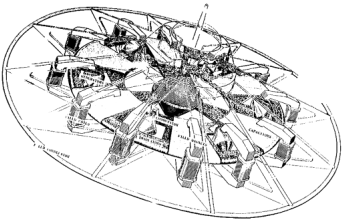
So if you connect a little exciter coil (a few winds of thick magnet wire for example) around a long pole wound coil of very fine wire, then you can connect it in either (+,-) or (-,+) to put the vibrating serpent-dance of static charged energy either on the ceiling, or the floor, depending on the polarity. And you can commutate it and make it alternate with polarity as it alternates with polarity! That secondary winding could be spinning, rotating, and gyrating to create an inertial field which is supercharged with high frequency through a static magnetic resonance which penetrates beyond the surface (like the vertical core -- see the big picture on the home page -- or another device). A magnetic field runs through the object, and so induction is throughout the object, so the energy of mass (and thus inertia; thus gravitation) is transmitted through a magneto-electrostatic field. <--- That is similar to Dr. Ning Li's theory of gravity-engineering on her design (See: Popular Mechanics article "Taming Gravity" 2003 I think is the year). Whereas she used a laser to raise the frequency of rotating mass in a magnetic field, I'm also using light -- as a paradox of magneto-electrostatic energy to do the same job. Actually that is what the OTC-X1 is doing, if it utilizes a spark gap, which it probably is in order to create a unified energy field.
That would have to be the final thing to consider as an aspect of "wiring," in order to electrically raise the frequency of an inertial scalar field.
Those are the finite combinations to test if the OTC-X1 doesn't work in a simpler way.
It won't be nearly that complex as all of that mess above for the OTC-X1, in actuality. It never is.
This is where research and development COULD lead though, branching off into these other areas in order to learn more about the universe, and what we can do with gravity-engine systems. (magneto-electrostatic resonance of electrostatic charged inertial fields; inertial fields involve spin, gyration, rotation of mass; acceleration field = gravity field according to Einstein).
That could also lead to Outer Ring Engine systems with two counter-rotating scalar fields.
13)
Final Wiring Plan:
The electromagnet moves over the utron, inducing a polarity of current to the utron, transverse to the motion of the magnet. The magnet will have to roll over the utron, like a gear that turns the utron into motion, so the magnet will have to reverse polarity sharply. It reverses its field when enters over the utron, and reverses it back before it leaves the utron.
The timing doesn't have to be precise, because a snap-reversal will induce a high volt collapse just the same as a break of the circuit induces a high volt collapse, only the snap-reversal will be a little "harder" of a collapse, but may cost more energy. The field collapse is induced into the utron (a bonus).
It doesn't take any energy to turn a circuit off and turn it back on. But a magnetic field collapse creates more energy in a single instant, then a stretch of distance of (using) normal electromagnetic current.
That collapse is harnessed in the utron to recharge the central accumultor (also with magneto-electrostatic energy in a spark gap) as the alternating current rolls over the top of the utron. Traditionally, a Schoolgirl circuit only requires one flyback of higher voltage to recharge the battery. But there's only one coil (the utron). And using half the utrons won't induce the other half, directly.
An utron field collapse may just be just like two coils wound over top of each other, but it's unable to induce itself, like a Bedini coil. So the only option is to use a "snap reversal" of the electromagnet field coil, so the reversing polarity of the electromagnet rolls right over the top-dead-center point of the utron. Actually the magnetic field spins, and just like how electromagnetic current is induced into a coil, that magnetic spin pushes the utron to also spin, at right angles (angular; transverse).
A fast field collapse of a magnet occurs at light-speed. We need a longer span of time to generate a high volt current, but in an easier way than just a discharge, but we need high enough voltage to bridge a spark gap inside the central accumulator.
There it is.
The central accumulator accumulates the living static scalar energy, "sparked into life" from the spark gap inside.
The Earth under my Tesla tower behaved like there was some spark deep inside the Earth, it was the same energy as that -- electrostatic energy. The Central Accumulator would develop a bio-energy radiant field similar to the Earth's energy field. This can be harnessed also by a secondary system (such as a special Tesla Transformer) with an exciter coil for the Outer Ring.
The Outer Ring will need a separate auxiliary input of magneto-static current. That input can be amplified using a Rodin coil, wound in interference like how Daniel Nunez does it at 1stopenergies.com has been demonstrated by Jamie Buturff in Sedona to amplify energy through resonance of sacred-geometry Pythagorean harmonics of frequency. In co-counter-rotation, maybe more, and harnessed through a cylinder-shaped Tesla style coil stuck through the middle (pictures forthcoming; book).
There is a bit of a current in a potential 3rd circuit in a Bedini engine, as seen in the video above. There may be a little energy left over in a third circuit from the OTC-X1 engine. This energy can be rocked in an induction coil to generate a very high frequency spark discharged, that can be harnessed as magnetic current. The faster the frequency (harnessed in capacitors and transformers) increases the current speed (cycles per second). I'm sure a way will present itself.
The energy can be amplified in both amps and volts.
UPDATE
Due to special request, I have pulled this video off of the home page in the video links in section 7, and posted it here on this much older article.
I don't expect anyone to ever really be reading this OLDER article too much, since most of the latest developments are up at the top of the page, however I realize it keeps showing up in the search engines more times than I would like.
All those little words up there at the top of this page are the various links to the website.
This article can be found on the Construction Blog page, which is the page you are currently on. If you click on the "Construction Blog" link at the very top of this page, you will see all the various articles all laid out in sequence from newest to oldest.
Here is the home page quote associated with this video link, uploaded by Mark Hoza:
"This video is an OTC-X1 replication video which shows that electromagnets can indeed spin a flat metal disk. It is known that a large C-shaped electromagnet will spin a copper disk. In the video, Benn's electromagnets do not have a "C" shape to make the disk spin, which is noteworthy. Benn's electromagnets may need to be larger, but the point is it's a great effort at reconstructing a historic working machine.. Could be that the capacitors have to be charged to generate a faster speed. The OTC-X1 in design also has the electromagnets spinning in the opposite direction. Just as a note, he is using solid utrons, and a solid core central accumulator. His video is just to test the motion of a disk spinning due to electromagnets, to show us that the principle does indeed work. He is using DC current configuration . . . Efforts of Benn of the Australian OTC-X1 pod, video released by Mark Hoza, tracked at the bluestarenterprise.com website"
Also see: www.clandestinedisclosure.com which is headed by Walter Nowosad, the unofficial manager and coordinator of the pod groups.
This is an easy concept to test using a c-shaped electromagnet with a copper or aluminum (non-ferrous) disk on a gimble, but the disk has to have electricity applied to it. The polarities are on the outside edge and toward the inside center, to get it to spin. See the "wiring the OTC-X1" video, also on this Construction Blog page.
BUT ... On Walter's video about this uploaded on the Bluestarenterprise website, it seems that this is actually being spun by hand! .... hmmmmmm... Each plate needs to be connected via wire, and there needs to be a half-transformer block around the electromagnets to get it to spin under power. Darnit!
This is what I've been talking about in various rants from time-to-time, that the "pod" building groups, the "OTC-X1 Engineers" are ineffective! Most don't have the money, and most are too scared of coming forward with videos because they're afraid of invention suppression, which is what happened to OTC Enterprises, and countless other inventors, tens of thousands over the decades who were suppressed. This is common knowledge.
However if you want to just have proof of the concept of the motor aspect, look up Forbes homopolar dynamo. I'll even post a photo of an example.
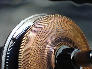
This is a homopolar (unipolar) dynamo. The concept is sound. Also, this has been tested by the same pod member who made the video above. He pulled out a capacitor plate, pulled out an electromagnet, wired them up, and it moved like it was supposed to, but heated up due to shorting along the capacitor.
He probably hasn't figured how not to heat up his capacitors, which is why he hasn't made a video of the motor moving.
To avoid this heating up due to direct shorting of your capacitors, see the top article on this page called:
Analysis and Principalities of the X1 Focusing on Rotating and Counter-Rotating Charges and Negative Energy
Update from the comments
In reply to Joa:
Something like this might work:
In reply to Joa:
Something like this might work:
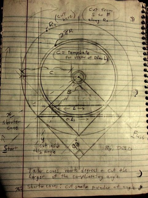
Image fixed. It now reads "for utron of Dia. L1" .. got a nasty light glare in the photo though . . .
A 90 degree utron cone of radius B (diameter of L1 - L Prime) is cut from S to F, keeping the material of width C along circumference R1 (R-prime; the outside circumference).
Don't forget to subtract for material thickness.
Since it's a 90 degree cone, it shouldn't have to be anything fancy I don't think . . . This is the geometry I can suggest, although I haven't cut it out on a large sheet of construction paper and thrown a framing square on it to check.
What this is for those who need to know: You cut out the pac man shape on a sheet of copper or aluminum or something (actually steel is best due to ferrous and non-reactive properties as we are finding out), and then you bend it into the right-angled cone shape for a utron half. You have to cut a hole in the center for it to fold into a cone properly.
Also... shorter cones cut X. taller cones cut Y. The taller the cone, the narrower the bird-mouth cut will be. Sorry if that wasn't made clear in the image. I thought it would be too self-evident, so I just left it as a vague note .. But now after coming back to it and looking at it and being confused about it, I just HAD to make this note. Obviously that doesn't matter since the utron is a right-angled cone x2. So that was just an afterthought I noted just to explain how you can derive your own utron sizes.
 RSS Feed