I've decided to use a style of Townsend Brown / OTC-X1 hybrid for the outer ring assembly.
The Outer Ring's function:
1) Negative energy field generator
2) Negative energy power output ring
3) It can spin or rotate, but is preferred to be in a fixed position
The Outer Ring provides power and flight stability, and field stability -- extending the field resonance from the OTC-X1 to the outer perimeter of the ship. It is a "field resonance" ring.
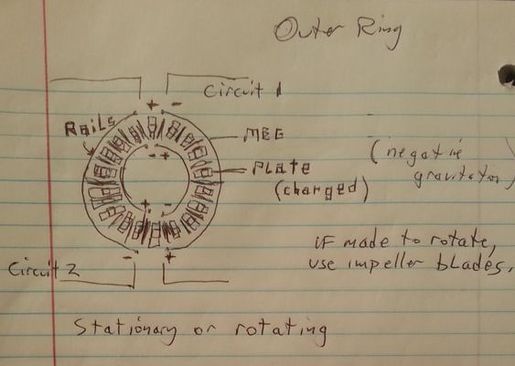
The Outer Ring is powered by many MEG-style devices (motionless electromagnetic generator) around the ring. Motionless is the key word, here.
Various coil assemblies can be used, as well as several different mechanical timing circuits; wiring-in-series; vacuum tube diode bridges (instead of solid state; the vacuum tubes have a little spark in them, so it's compatible with negative energy); and hemispherical circuit architecture.
This is a better framework, using di-electrostatic plates between MEG "heads." Internal "super permanent batteries" can be used to add that little bit of energy to the MEGs to start pushing it all up into vacuum resonance for high frequency and wattage output (providing power to the whole ship, including extra power to the OTC-X1).
The circuitry and commutation and polarities from the energies can be much better regulated if the ring did not move! The segments and sections also can be grouped to hull charge plates (for better stick and rudder type of maneuvering, and/or better power regulation).
This is just a basic framework, but is more logical than using coils in this instance. Also, this is a fixed point of reference. There's enough rotating parts inside the ship that a fixed point of reference would be welcome, since the main hull is not going to be spinning around, but only the lower part at the OTC-X1 engine.
Also, since electrogravity plates can work in a hard vacuum (https://arxiv.org/pdf/1611.02576.pdf), then there need not be rotation for the charged flight surfaces, particularly since the charged flight surfaces would cause the ship to rotate left or right and be steered -- much better handled from a fixed point of reference.
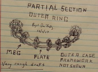
The plates intersect the zero midpoint of each MEG (they're in the middle).
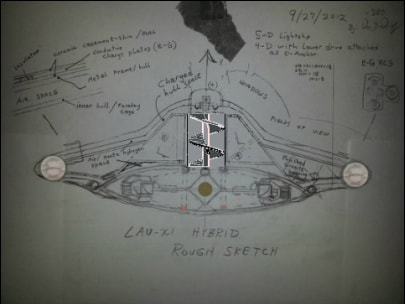
The outer cage framework, shown in the articles below, fit around this assembly.
Negative energy field generator and power generator. Same as OTC-X1, but motionless, and without central core. The impeller is the outer ring's central core.
Di-electric plates resonate with magnetic current between MEG central cores.
"power steering" for the impeller.
~ . ~ . ~ . ~ .
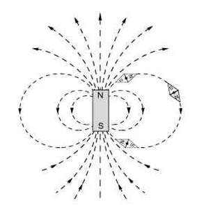
The MEG is oriented vertically as seen in the image below.

UPDATE ON THE MEG:
It appears that the MEG actually is in DC configuration. The coils create an electromagnet in the same polarity as the magnet in the middle, the reflective magnet. The static energy from the coils mesh with the magnetic field at right angles; rectilinearly. When the electromagnetic field collapses, magneto-electro-static energy waves are transmitted at right angles to the alignment of the north-south pole, in parallel to each other. The electric-static field fills the "spaces in between," moving in the geometry of the "disintegration of mass," relative to the magnetic field, essentially fitting like gears, together. However you want to look at it, the central magnet resonates with each hemisphere; and when the hemisphere switch to the other coil is made, the central magnet is still vibrating with electrical energy, held in the magnetic field -- because it holds and transmits and resonates electrostatic longitudinal and parallel waves, through the magnetic field. This actually causes the magnetic field to move faster than its waveform allows, too, because the magnetic field, separated by two most distant points will conduct through the electrostatic medium, giving the electrostatic field a MAGNETIC quality.
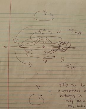
If you look at the drawing of the MEG Outer Ring segment above, the central magnet carries its lines of flux around the bubble in the most efficient way possible. So from a point in the middle central magnet, to a point on the outside edge of the field, between those points longitudinally, magnetic energy will conduct IN BETWEEN energy wave crests, in-between the troughs of the sine wave, breaking the continuity of frequency (time), and effecting everything that vibrates with electromagnetic energy (all matter) in the vicinity of its negative energy field.
This makes it infinitely easier to wire the Outer ring MEG to plate connections (the plates are horizontal, in the middle of the outer ring, in between each MEG).
~ . ~ . ~ . ~ .
These are various notes, I particularly wanted to note the hemispherical type of circuitry and geometry that the SSP also uses. Rotation can still be achieved by rotating charges through a cage, or through disks or half-disks around the outer ring space, but the hardware should remain stationary, otherwise it won't be any fun to wire up a complicated rotating engine.
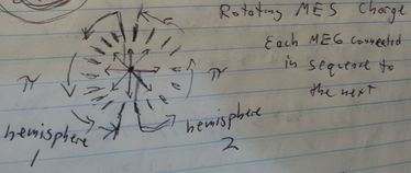
Charge orientation and circular field flow is divided in half, otherwise there would be a start point and a finish point at one point around a circle that breaks resonance.
The di-electric plates can actually double for capacitors in this case. The MEG uses vacuum technology, and so the ring itself is a negative energy field generator. The magnetic core however accumulates more of the bulk of the negative energy charge, like the OTC-X1. The flat plane where the plates occupy, around the disk, is geometrically aligned with the MEG "generator heads."
I'm trying to get away from requiring the outer ring to actually spin, because then a lot of variations can pop up, and a lot more variables and unknowns. If required to spin a north/south magnetostatic field, that can be done through field coils, rather than attempting to move the whole assembly. Also, it would make it easier for testing, to just spin field polarities, instead of actually spinning hardware.
To elaborate on that, the only way to spin the outer ring is to use magneto-static fields, since to use electromagnets would destroy the negative energy field shape by introducing positive energy in the ring. So, making it a physically-rotating assembly is out of the question! Also, if using large magnets, then it defeats the purpose of using the OTC-X1. This outer ring powers the "warp core," the vertical impeller engine, so the field shape needs to already be established throughout the ship at that point, and the outer perimeter of the hull needs to be using only negative energy. (the rapid collapsing of electromagnets is a frequency of negative energy, so the MEG and the OTC-X1 electromagnets do establish the outer edge of the field itself)
The outer ring will generate more power, the more of a load drawn -- that is a feature of a MEG, and likewise most negative energy generating technology, including the Tesla tower Ley-line
(the land-based system -- Tesla tower Ley-line -- will pull a constant current flow on a load, until that current is broken, then the power isn't there anymore until the system charges back up and spins it up again; in the new configuration this problem will be avoided, but it's very similar to Keshe's Mag-grav generator, at least the earlier models).
Negative energy has certain characteristics. The Outer Ring can also charge the OTC-X1 central accumulator more, not just through the impeller, but independently, in case the OTC-X1 needs more of a high-powered field to handle the extension of the hull past the OTC-X1 electromagnets.
The purpose of the outer ring is to generate power, and a field, but also mainly deal with static fields, and/or rotating static charges around conductive di-electric plating.
A "static ring" like this should be more than adequate. If it just requires moving magneto-static charges, then the impeller can be simplified, so that a charge moves along the conductive surface, instead of the conductive surface suddenly generating a surface-charge -- sending a moving charge along a rod, for example, is more valuable than sending a moving charge through a series of plates, to simulate a movement of charge. A full sine wave is more desirable than a broken imitative sine wave.
Since John Searl's craft shut off a section of charged hull to steer his craft, then I'm thinking a non-moving static ring is the next step toward simplicity and power, and electrogravity warp drive.
Having the outer ring broken into segments also won't confine the OTC-X1 operation. A craft that doesn't have to gyrate or spin, to fly is a solid foundation for a variety of electrogravity or antigravity achievements. It if can be handled through narrow plates, then craft don't have to be big and bulky.
Air / plasma is free to flow through the outer ring assembly through the inner hull air space.
If it does have to rotate, then using rail-gun style or other magneto-static style of rotation to spin the whole assembly could be a very useful thing to do; but if we can avoid that, then it would be better for testing and experimentation.
I think this simplifies this whole system, now, so it can be something that can grow from here. It's a bit unusual, but I don't think the plates in between the MEGs have to spin or anything (like a Dr. Ning Li device), because the Townsend Brown di-electric does NOT have to spin, and it has been seen to work. Is it the most efficient? Not necessarily, but the hull is a solid non-moving shape. Adjusting the magneto-static field around the ship is a great way to move it around, and it doesn't have to be openly exposed to air, but the high-volt charges can be behind a ceramic outer-covering, that still conduct the magnetic field (magneto-static field), but without a high-volt shock or discharge that can short out parallel plates.
There's other styles of antigravity, like David Sereda's design, which was confirmed by tests in a French lab, but this (the outer ring) has the least side-effects and environmental disruption or destruction (no ill effects to the environment). A single MEG can generate enough of a static field conducted along surface plates to easily lift a small light-weight static air-frame for testing and remote-piloting, which has been done by my mentor, years back.
So, this is a fairly valid concept. I wish more coils were involved to give the outer ring more resistance so it can power a stronger load, but it is expected to generate AT LEAST tens of thousands of magneto-static volts, with corresponding high amp output. What makes for good power steering at high speed flight is a good static ring around the ship, to change the electrogravitational forces and negative energy densities. Bob Lazar's ship worked with an electrical plasma field conducted around the hull, but it was radioactive, and wasn't ET technology -- it was German from WWII, from Victor Schauberger's Haunebu III.
Internal transformers and mechanical timing heads would have to work in tandem with the outer ring, too. This is one of the original ways Tesla had achieved antigravity or electrogravity levitation, by just using static charges, or rotating static charges around the hull.
The outer ring follows a Tesla / Townsend Brown style of hybridization.
This is the basic framework for the Outer Ring assembly.
--> See the comments to this article, too. ......
Vertical Impeller and Outer Ring Update:
I'm going to transfer some of the comments to the main article... Sometimes I do this, but sometimes I leave the good stuff in only the comments.
New Outer Ring framework.
The framework is a lot like the core. If the core is complete, then the whole thing can be derived from it. Improvements can be made, but the core will always be the same.
The simplest form of electrogravity is to align magnetostatic charges in a surrounding negative energy "warp bubble" as they are calling it these days. This will do the job and power the main engine, and power the "flight surfaces" for maneuvering and "power steering." The ring is like Iron Man's but way different. Lol ... it also floats. It will float because it's a negative energy field, not because the plates push it or pull it.
Basically (in the MEG), the magneto-static resonance is an active vacuum resonance, vibrating between the outer oscillating electromagnets and the central magnet. It creates the negative energy field and tremendous power output without any moving parts.
Some MEG systems also are able to output 5 or 6 hundred times the input.
Special battery construction will be included, for permanent batteries. However through a self-oscillating system, which builds itself up and up and up, the power output will far exceed the small start-up energy from a permanent battery electret.
The trick there, is to use the output energy from one MEG to power the input of another, and cycle it through itself, while pulling a load such as charging plates. Likewise with Bedini systems, batteries can be easily managed.
It is also possible for the plate construction to be layered metals sandwiched between dielectric electret materials as batteries to power the MEGS, and to conduct magnetostatic energy across and through the plates. In fact, this is much more logical, and with a magnetic plate layer as seen in the link in this article, the magnetostatic field can gain additional resonance in negative energy. This way, the outer ring can be self-powering and conserve interior hull space. I like this idea. It's like a Tesla tower Ley-line, in a circle.
The vertical impeller can also churn up a static charge in the cylinder housing for motion. If the impeller also uses T. Brown plates too, then it's a double whammy. ... the concept of the vertical impeller itself is pretty easy to grasp. I had visions of such a system when I was 8 years old. ... if anything new about it comes up, I'll mention it .. or just save it for a much better organized and simplified book which will include the permanent battery designs.
When you include an inertial resonance and frequency, with the magnetostatic impeller, within the resonance cavity of the central vertical core, then you've got compression at one end, even better than the cone-shaped EM drive. Not to mention the negative energy mass plasma/particle flow that the warp drive engineering page talks about.
Obviously, you can look at the MEG as a negative energy Transformer, which transforms positive energy into negative energy.
Of course now with the completion of the OTC-X1 physics, and the outer ring design, pertaining to negative energy inertia, the outer ring provides that zero inertia field the Warp drive engineering page discusses. It's done thru field correlation and magnetostatic vortex dynamics.
It makes it a lot easier than using heavy exotic mass rings. It's the same principle, but instead uses negative energy physics instead of Einsteinean physics.
It's an easy switch to flip from positive to negative ENERGY. Positive inertial gravity to negative energy gravitation. Metallic hydrogen would be a good thing to try as the conductive exotic plasma/gas.
This is difficult to work out a pure form of vertical impeller physics. Drawing a magnetostatic active vacuum is the easiest way to describe it. You just gotta remember we're not dealing with positive mass frequency anymore. Understanding it becomes easy and intuitive after a while. That's the ideal place to be in one's knowing.
The scaler longitudinal wave carries an electromagnetic energy much faster than its wavespeed. So you are compressing negative electromagnetic "time" in the vertical engine core. That is literally an ANTI-gravity impeller.
The outer ring specifically deals with the warp drive vertical engine and field shape. So it is relevant to discuss the impeller in this outer ring article.
Hope you can forgive my crappy drawings here in this article. The plates are centered in the middle of the ring like the OTC-X1 plates. Centered at the intersection with the MEG zero magnetic point.
Keep in mind, the vertical impeller pulls the ship up, as seen in the orientation, in the image above. It doesn't create a "thrust" reaction, but instead it draws a "vacuum electrogravity." It's the same effect as perpetually falling into a pocket of gravity above the ship, similar to how Viktor Schauberger did it with the Haunebu III (Bob Lazar's famous "element 115" back-engineered craft), but very different -- without radiation or positive energy forces, or energy losses.
Adding more of the comments:
Be sure to check the comments below, however, for the double-coil method for tuning a magnet, and other frequency secrets and Tesla public-domain resources.
I do want to share this, though:
A single pole (characteristics of negative energy is just one-polarity) of electromagnetic current is run thru the scaler longitudinal energy field of the horizontal plates through the middle (of the outer ring) between each MEG. Cutting the wavelength in half, electromagnetic polarity can move in a straight line, and it cuts its time in half ... when time is cut in half (the waveform of electromagnetic frequency), it breaks continuity. If there is no continuity, time is not defined.
You could say the electromagnetic wave cuts ITS time in half, but that's going to carry a frequency of time throughout all things that have electromagnetic frequency, which is all matter.
~ . ~ . ~ . ~ .
Unified Proof of Concept and Negative Energy Unity within the Framework of All LAU-X4 Engine Physics:
Gonna pull more comments out and organize this into the article, so hopefully such a general framework of negative energy unity can be easily referenced all in this one article.
I'm going to organize this into parts:
General Construction Details:
because this is perhaps the most complex engine of the ship .. you CAN use a spark gap like a diode so that only the electromagnetic collapse is carried to the plates, excluding the positive energy electromagnetic "fill" of forming the magnetic field in the coil. (wiring only for negative energy)
That worked successfully in my Tesla tower system in fact.
I've had the benefit of seeing the MEG actually work .. and have exposure and experience with this technology. It's not as hard as you think. The MEG has easy input/output terminals. Tune it at 42 megahertz. Tune the magnet to the same (the double coil method). I explained that somewhere in the comments.. otherwise, it will still work. Just play with it.
The shape of the MEG can be modified a bit so that the coils are wound around a straight section of the ring, because winding coils around a ringed shape would be a really poor coil, and we can't have that, with the increased power output from the new frequency tunings.
The Double Coil Method for Tuning a Magnet:
Resonance coil. Stand it vertical. Put a stick on top, set your magnet on top of the stick. The resonance coil has AC frequency going to it. The magnet will want to fall down. When you hit the resonance frequency, the magnet will vibrate back and forth but will stay balanced on the stick.
Now drop the magnet down the coil and rest it on top of another coil (coil 2). With coil 1 running at set frequency, hit coil 2 with 42 megahertz, just a quick pulse.
Tuned.
My mentor taught me the double coil method. 42 megahertz is the baseline frequency of our local star system; rather baseline frequency harmonic in resonance with the galactic core.
Tuning your Coils:
Another frequency secret.. once you know your magnet's resonance frequency, you can tune your coils to that frequency. Tesla had a rectilinear approach to that. If you know a wave frequency, you can make a loop of wire that matches the wave frequency. The wave has height and shape, and you can graph that to determine the size of each loop of a coil (diamete, circumference, number of loops in a linear distance that equates to resonance harmonic of the wave you want to receive) Take a straight wire, divide it in segments which is the circumference of each looped coil winding turn ... that same straight wire can be a single loop or multiple loops in a coil that measures the same as the wave frequency.
Tesla's Colorado Springs notes are in the public domain now. Well worth finding! He gets into this in his notebook. He also writes about transforming matter and energy states. So ... this stuff is starting to get pretty interesting.
Engine Physics:
... also, as I mentioned on the Construction blog page, the MEG levitates when a large inductve load applied such as a large transformer - a transformer on the output line to a load (such as the electrogravity plates).
That's how Tesla did it. The higher the frequency (using a Tesla transformer), the craft went from low frequency hover (green static color) to a fast travel speed (violet).
That is super important because the MEG under testing conditions only levitates when under large transforming inductive load. Actually, its the resonance load of the transformer, which is responsible for the MEG to ice up and levitate.
Two Tesla transformers control the frequency of each outer ring hemisphere, of the electrogravity negative energy output to the the plates AND upon the MEGS. <--- Tesla transformer acts upon its energy creation, and its source.
So the transformers are between the MEG and the plates in circuit. There will have to be enough room for transformers in the saucer aeroframe.
This technology theoretically outperforms SSP heavy exotic mass ring technology, and provides more reliable field stability ... This is purely a biological field interface, "wirelessly" ... it is designed with compatibility to the Human energy field.
Of course, power level adjustments and directional flight controls are part of the pilot interface. Pilot won't experience inertia. And the addition of the vertical impeller may make the journey easier to remember due to those field geometries.
The outer ring may help stabilize memory issues too. ... that's a little too beyond the subject of this article.
The pilot must be conscious of the journey, traveling through discontinuing time with broken continuity. The pilot makes his own time, and all occupants must be aware if their temporal target destination. That will maintain a conscious framework thru temporal displacement.
I wouldn't leave the field on for extended periods of non-use. Don't push yourself beyond what you think or rather what you feel you can handle....
Artificial or on-board gravity:
It is assumed that the gravity field of the Earth is held in resonance as long as the outer ring is on, at least, or as long as the OTC-X1 is idling. Like how a magnetic field is set into a piece of iron ... but may become demagnetized or re-magnetized by sufficiently larger nearby gravity fields.
Negative Mass:
When the mass of the central magnet is fluctuating in positive and negative energy (considered exotic energy and exotic mass), which is caused by the scaler longitudinal wave from the collapse of the electromagnetic field coils to momentarily also collapse the central magnet's field (also this energy is conducted magneto-staticly thru the transformer block), then the central magnet itself converts to AC negative energy. AC negative energy is exotic.
The mass of the magnet becomes a negative mass in AC-negative polarity. .... that's where the vacuum energy comes from. The levitation of the MEG is electrically achieved by reducing the mass of the magnet to a negative electromagnetic value. This is proof of concept.
When the magnetic field from the MEG central magnet electrically collapses, and then rebuilds on it's own force in rapid oscillating frequency, under those conditions is when the mass of the magnet is a negative value (negative energy). It's like Searl's engine.
The alternating of positive and negative ENERGY is what I consider AC-negative or EXOTIC energy. Positive and negative form ... <--- This is highly significant; and is a requirement for stargates as well as hyperspace jump drives (teleporting in a series of very-long-distance space jumps, which is how a "beam ship" is described).
The vertical impeller:
It delivers a negative energy pulsing, a frequency beam of negative gravity. Do you see how negative energy leads to negative gravity? By changing the frequency of time, a gravity wave is produced.
The vertical impeller delivers pulsed and spiraling gravity waves, specifically negative gravity waves, and in a beam due to the rectilinear nature of magneto-electrostatic geometry. This is the nature of tugging on the scaler vacuum, as these physics describe.
Electrostatic maneuvering:
Under negative mass levitation, the static force is what moves the ship. The static charge at one side of the ship pushes the ship in the opposite direction. That's how John Searl's craft moved. Townsend Brown's were very similar. You can look at negative energy propulsion as "like squeezing a pumpkin seed in your fingers and it shoots across the room" -- as my mentor has described it.
Hull polarity too .. electrons flow to positive. And with negative energy, the energy amplifies flowing over an electrical radiant hull.
The Tesla-tower Ley-line will put this system to the test, and has already proven results. So .. It's like the Earth's surface in a way, the hull is. ..
I want to note hull plating having a conductive magnetic layer and a dielectric and/or metallic conductive layer. And a thin ceramic insulative layer that can conduct a magnetic field (possible the outer skin may be the choice for the dielectric) that can conduct a magneto-static negative energy SINGLE POLE static current in the vacuum of space. It will have to be insulative to touch, to keep plates from building up carbon and shorting out, when flying in an atmosphere, particularly polluted cities . . . (Tesla wrote about that, too)
The higher the frequency of negative energy magnetic oscillation is lower field of negative mass.
This is important. This is hull construction for the negative energy framework. A single magnetic layer will do because only one pole is being used.
Other plate structures like in the three engines will all be slightly different.
I will have to publish those details. Keep in mind, this has been published upon such Townsend Brown style flight in a vacuum: https://arxiv.org/pdf/1611.02576.pdf
Engineering specifications and numbers:
When you think about how the vertical impeller can work .. the hull space can be charged for shielding ... just awaiting the impeller to turn on and start "churning up the static charge." .... The outer ring is supposed to handle those power requirements. At high frequency, not a whole lot of negative energy is required for this.
Considering the outer ring has a whole lot of very large MEG's, in a field-efficient core, with tuned magnet and coils, it's going to be a very large output, and will generate more power under load.
I'd say about 70% of the saucer outside the cockpit area will be nothing but power systems, transformers, timing controls, battery/capacitors, etc .. But with enough area in between can house other equipment such as air-recycling filtration, water, circuit breakers, some pressure-vacuum tanks and pumps, spaces for landing gear, with very minimal space for crew needs like berths, head, and galley. ... at least that's what it looks like for a small craft.
Truly if all else fails with the permanent battery construction, which .. they're out there ... then Bedini systems can be employed to cycle batteries and/or capacitors, for sustainable battery systems. I'd prefer to go for a permanent battery, though.
With the vertical cones engine, there was the possibility for the cones to also generate power, especially if applied to a Tesla / Bedini circuit. However, I believe the impeller to be faster. So, that would require permanent batteries, because there's just not enough room for much more equipment.
The MEG is PERFECT in this application .. and I do have a few ideas for permanent battery systems based on similarities with Earth batteries (again, working from the land-based radiant energy support angle) .. which actually some have been handed down to me, ... The polarities.. well .. let's say this will be handled later. The more powerful a permanent battery/capacitor is, of course the better. It would be nothing to see a 10,000 watt output from one single MEG from a small 12 volt, 10 amp electret (permanent battery). Those are the realistic numbers. Worst case, you'll see 1,000 watts from a 12 volt 10 amp battery.
Worst case is actual results from a rather surprisingly small MEG ... Just think of the resonance pumped up from larger units with more efficient core shape (eliminating eddy currents, and lessening the need for laminate material ... capable of achieving a much higher resonance) ...
Bigger isn't always better. Usually bigger equals more resistance. However, with a large enough power supply to drive the initial energy into the MEGs, then the MEG will drive itself and amplify. It's not impossible.
The power output of the Outer ring is in the general ballpark, from actual tests on individual smaller units is anywhere from 40,000 to 400,000 watts. That's with a power supply of 8,000 watts, of standard positive energy. So, weight can be reduced by using dielectret plates in the outer ring (di-ELECRET), and there's several places in the inner hull space for capacitance built up in "guide channels" of plate stacks for exotic gas flow (plate construction details will use alternating materials, to be released later), ....
But also one MEG will create enough energy to power itself. So the battery weight can be very low, only needing about 1,000 watts to kick-start the MEGs into resonance. Like a starting battery. The only power needed is to run a timing circuit, which is a very tiny amount. Remember the MEG kept itself powered for a couple minutes after all input power was turned off, as I have said before, oscillating all by itself.
Also, mechanical timing circuits (my personal preference) would not use much power, either.
Plate construction in the outer ring can use magnetic layers, in Tesla /Townsend Brown style; and since we know a magnet can create an exotic energy field, then we have a decent power system here.
When you consider how heavy John Searl's craft was, the OTC-X1 and outer ring are made for handling weight! That is - a lightweight engine able to haul a good-sized weight load.
Boatbuilding skills and knowledge work well in this application.
The electrical energies will easily migrate to each system, if they are made to field-resonate with each other. Keep in mind there's open spaces between the engines - they are not closed systems individually.
This means 40,000 watts is distributed with zero loss throughout the ship and holding that energy density on the hull plating. 100,000 watts should be a good target range to strive for, minus the energy output of the OTC-X1 (it generates its own power).
Vertical Impeller to OTC-X1 Hookup:
The OTC-X1 is the negative energy ground (will meter as a positive electrical-radiant, or electrostatic charge, OR apparently as the Construction Blog shows, the Central Accumulator should read as a north-positive, and south-negative magneto-electrostatic polarity, but will otherwise be a negative ground).
This allows for the top of the Central Accumulator to isolate a single pole. The vertical impeller connects to the top of the central accumulator, either by lowering it into a transmission or otherwise, and also with the option of using a metal iris to open or close the static flow between the two engines.
Originally, the top of the vertical core contained a Tesla coil; that can still be employed, and I wanted to mention this in case it wasn't too clear.
The vertical impeller connects pole-to-pole the Outer Ring to the Central Accumulator. Now this is where it gets a bit peculiar: The outer ring much complete a circuit through the vertical impeller (a return path from the bottom of the impeller to the outer ring), however the OTC-X1 completes the circuit with the Outer Ring, connected by just one pole. The return path of electrical flow is completed through the negative energy field.
A little resistance can be added here by making the return path from the impeller to the outer ring through only the plasma/exotic gas inner hull circuit; likewise, the Tesla coil up top initiates the flow through the vertical core. With added resistance, negative energy will flow more superconductively.
My point is that the impeller acts as an antenna to the central accumulator. There will be engineering details of the top connection to the impeller later. It's just a toroid field connection to a vertical shaft.
In this sense however, there can be some separation between the OTC-X1 and the outer ring; however any more details at this point is going to impede the overall framework ... I want to emphasize the separation between the outer ring to the vertical impeller, as this circuit is purely connected via field induction.
The bottom of the central accumulator can connect to the hull plating, and complete the connection through the hull plating to the outer ring (in addition to other connections to power the hull plating). This should be hemispherical. The bottom of the central accumulator to the outer ring, through that section of hull, and then from the outer ring to the top of the impeller, through that section of hull, these return paths can take such a route.
Connecting the impeller through one-pole to both outer ring and central accumulator engines, is a characteristic of negative energy . . . This also means that as the energy runs through the pathways, more energy will be generated, and in resonance. The frequency of the electrical currents are also part of the resonance harmonics.
In warp drive full speed ahead mode, the outer bottom hull plating between the OTC-X1 and Outer Ring will tend to resonate more, as far as the energy static characteristics go (the outer ring and OTC-X1 will resonate through the hull plating circuit and build up energy thus). However, the outer hull plating from the Outer Ring to the top of the impeller will be directional, and a current will flow quickly.
That may seem weird, but since the Outer Ring is electrically anchored to the OTC-X1, then the Central Accumulator acts as a common ground. Resonance will occur between the two energies and fields, even though a current flow through the outer hull plating may be directional, as well. This resonance can be seen like how a Tesla tower creates earthquakes in an area, as the energy resonances with the Earth surface, even though current may flow from the ground up through the tower.
This also enables the vertical impeller to act as a receiving antenna, not just receiving energy from the outer ring, but also from the universe and space that is in front of the impeller . . . and again, the outer ring is functioning as an accelerator.
^--- This. ~.~.~ This is where the active vacuum is drawn through the receiving antenna, pumping up the Central Accumulator to the "electrical water chi-bubble" feeling of how energy gets when it does that. This is when a WHOLE LOT OF ENERGY is produced.
THIS is how the vertical impeller also generates energy, or acts as a generator -- through the acceleration of the active scalar vacuum. (It *IS* a scalar vacuum)
This completes the core design of the LAU-X4 hyperdrive starship -- By: Administrator, Drew (12/03/2017)
~ . ~ . ~ . ~ .
Afterthought:
AC MEG connection, just because it's too easy.
AC negative, which is the alternation of positive and negative energy (exotic), can be in either DC OR AC configuration. The principles in physics will still remain the same.
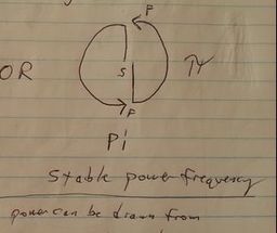
AC mode actually can be used. I just want to make a note of this. Doing it this way would evenly distribute energy to the ring and plates; and the same principles of physics would apply. This would be a huge dynamic ... the static aligned north/south magnetic field would be transferred to the plates, while the MEG central magnet flips; the magnet could act as a diode (or gate), but it holds a stability of alignment within an oscillating and alternating frequency of collapsing electromagnetic currents.
Similar to John Searl's in a way...
If you can see how it works in DC, you can see how it works in AC. it's not hard. The north south poles on the top and bottom of the transformer core would be flipping in negative energy polarity, around the permanent central magnet, while it also acts as a diode to keep the left and right hemispheres in resonance, or otherwise allow current to pass only on the top or bottom . . .
Like I said, it's a huge dynamic. There's publications from Tom Bearden about the MEG, which should explain its operation.
Another benefit in AC mode however, is due to the directional lines of magnetic force. The circulation dynamics of the field flow have to be noted, because this is a real dynamic of a magnet. The magnetic flow around the circle (over the surface of the Earth) should be from south to north, as measured from the northern hemisphere. So this picture is backwards, but I'll use it as a reference, anyway:
Otherwise, an alternating current flow from coils in just a ring-shaped transformer block without a central magnet would oscillate a north/south pole on top and bottom. So this magnet to the left could be flipping around upside down and rightside up, or RATHER, an AC frequency of negative energy can be applied to the central magnet which matches the magnet's resonance frequency, so that it vibrates and shakes with a large field output of combined magneto-electrostatic energy <--- similar to how a magnet is tuned.
This is another way to harness energy from the vacuum.
These same mechanics apply to the Tesla tower; and the energy harnessed from the active vacuum (free energy; abundant energy of nature) is static in nature, and can feel like "warm electrical water." Also the same thing involved with the Tesla tower is involved with the plates.
There's a secret involving AC and negative energy and massive power output, which also links to electrogravity that may or may not be this very thing here. This overall framework certainly does make use of alternating energy phases.
 RSS Feed