Freshly updated: 11/30/16
I want to make note of a few things.
Casimir plates, or rather di-electric plates which actually hold usable energy. We see that aspect in the OTC-X1 accumulator frame (rotating central disk) where there are two plates dubbed "capacitor plates" but are really more resembling di-electric plates with a material medium between them. The main purpose is to induce motion electromagnetically, to get it to spin. In the Tesla Free Energy page di-electric plates are also discussed, to reflect longitudinal waves, building up energy. It resembles capacitance, but it's a little different. Dr. Dan Nelson, creator of "The Water" had made an encoding laser powered by "virtual particles" -- a free energy laser -- which also relates to a negative energy power source.
I am not fully informed about this aspect regrettably, but it is something that makes sense to me, intuitively as di-electric resonance between two conducting plates. Townsend Brown also applied this concept to achieve his famous electrogravity discovery.
We see this again in the outer ring. The article below this discusses the di-electric plates across the diameter of an electrical accelerator frame around the perimeter of the LAU-X3. The deal with a transformer though uses an electromagnetic field circulation, in transverse. I'll illustrate. Magnetic field circulation is part of a transformer component. When the circulation is broken, it becomes inductive. The circuit is completed through an energy-field medium, rather than a solid conductive medium. Recall in the Tesla Engineering Physics page, an electromagnetic current could wirelessly be conducted through an electrostatic corridor with ease. That corridor in my experiments was a good 50 feet long, but a single AA battery conducted through it.
In the diagram, A and B are to note. In diagram A, the coils are wound so that where they touch, they travel the same direction. The coils rotate within a magnetic stater, and if they were wound oppositely, they would phase out to zero current. But in diagram B, in a resonating circuit where diodes are used to control the flow of electricity, they are wound in the same directions; but where they touch, they are in opposing flows, and yet the circuit is considered to resonate.
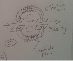
In diagram C, in the top half of the transformer, there is counterclockwise flow, and clockwise in the bottom half, so in the middle the currents are traveling in the same direction (at the same polarity) and thus augmenting each other.
I want to make note of a few things.
Casimir plates, or rather di-electric plates which actually hold usable energy. We see that aspect in the OTC-X1 accumulator frame (rotating central disk) where there are two plates dubbed "capacitor plates" but are really more resembling di-electric plates with a material medium between them. The main purpose is to induce motion electromagnetically, to get it to spin. In the Tesla Free Energy page di-electric plates are also discussed, to reflect longitudinal waves, building up energy. It resembles capacitance, but it's a little different. Dr. Dan Nelson, creator of "The Water" had made an encoding laser powered by "virtual particles" -- a free energy laser -- which also relates to a negative energy power source.
I am not fully informed about this aspect regrettably, but it is something that makes sense to me, intuitively as di-electric resonance between two conducting plates. Townsend Brown also applied this concept to achieve his famous electrogravity discovery.
We see this again in the outer ring. The article below this discusses the di-electric plates across the diameter of an electrical accelerator frame around the perimeter of the LAU-X3. The deal with a transformer though uses an electromagnetic field circulation, in transverse. I'll illustrate. Magnetic field circulation is part of a transformer component. When the circulation is broken, it becomes inductive. The circuit is completed through an energy-field medium, rather than a solid conductive medium. Recall in the Tesla Engineering Physics page, an electromagnetic current could wirelessly be conducted through an electrostatic corridor with ease. That corridor in my experiments was a good 50 feet long, but a single AA battery conducted through it.
In the diagram, A and B are to note. In diagram A, the coils are wound so that where they touch, they travel the same direction. The coils rotate within a magnetic stater, and if they were wound oppositely, they would phase out to zero current. But in diagram B, in a resonating circuit where diodes are used to control the flow of electricity, they are wound in the same directions; but where they touch, they are in opposing flows, and yet the circuit is considered to resonate.
In diagram C, in the top half of the transformer, there is counterclockwise flow, and clockwise in the bottom half, so in the middle the currents are traveling in the same direction (at the same polarity) and thus augmenting each other.
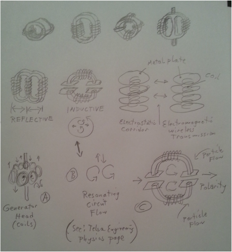
Tesla used AC (Alternating Current) systems. So in (C), resembling the outer ring, it is set to oscillate (Alternate), which builds up a magneto-electrostatic charge between the plates. Due to the alternating current, there is a magnetic collapse involved. It is the collapse which is most important, because in that moment is the highest amount of energy. The collision not of AC energy, but of the negative energy of the magnetic collapse in AC occurs with a DC positive energy. That is the key to generating exotic energy.
Particle flow will spin in a magnetic polarity through the outer ring, according to (C) counter-clockwise in the top segment, and clockwise in the bottom segment and travel in opposite directions. Through the diameter, a special di-electric is placed according to Townsend Brown's discovery, for that specific purpose.
This may seem rather mundane, but there is a critical element left out, otherwise it is entirely explained as it should be.
Further discussion:
Wind a coil of magnet wire, and connect a battery. Depending on the polarity, it will make a north pole on one end of the coil, and south pole on the other. Also depending on the direction the coil is wound it will determine the magnetic polarity. Look at figure (C) again. Particle flow in one direction will create a north pole in the top hemisphere, while particle flow in the opposite direction will create a south pole in the bottom hemisphere. Also, it will create a positive charge in the top segment, and a negative charge in the bottom segment. It is that positive and negative polarity which interacts with the di-electric across the diameter. Positive on one side (top) and negative on the bottom, is where electricity will flow through the Townsend Brown di-electric across the diameter (which is not shown in the diagram).
In a common magnet, the north pole and south pole are in different polarities. From the zero point in the middle of a magnet flow is in opposite direction toward the north than it is toward the south, even though in a coil, for example, it is wound in one direction throughout.
Look at the flow arrows in the diagrams. In the top left transformer, magnetic flow is in one direction around the ring, say it's a clockwise flow. This means that if the ring is divided in half at the diameter, the top half of the flow is in the same direction (clockwise), and the bottom half is in the same direction (clockwise), and so in the middle, the flows go in opposite directions, phasing it to a zero, which is why there's not much of anything going on in the very center of a magnet.
I'm not trying to point out the obvious for the sake of the obvious, however. In the generator head (A), the current flow of side-by-side adjacent coils must travel in the same direction where two side-by-side coils touch, otherwise the generator wouldn't work; it would cancel itself out as the coil sides passed over a magnet. Again, the obvious.
What I want to point out in (C), is the positive or north pole in the top hemisphere, and the negative or south pole in the bottom hemisphere (I'm using those polarities as a reference for ease). Across the diameter, there is definite polarity from one side to the other. There is however, definite polarity on the top set of plates and opposite on the bottom (because of the clockwise and counter-clockwise flows in each hemisphere).
That is not a standard transformer configuration. Yet, instead of bringing the whole circle to a zero energy generated, it gives the circle polarity, which is what generates energy. The diameter through the ring is where the action is. That mimics the polarity also of the north and south rotating magnetic field of the OTC-X1 peripheral of electromagnets.
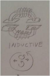
The energy overall is then collapsed from the top and bottom toward the center diameter. That configuration is different than in the second image from the left in the second row from the top, labeled "inductive."
Those two differences should be noted.
Particle flow will spin in a magnetic polarity through the outer ring, according to (C) counter-clockwise in the top segment, and clockwise in the bottom segment and travel in opposite directions. Through the diameter, a special di-electric is placed according to Townsend Brown's discovery, for that specific purpose.
This may seem rather mundane, but there is a critical element left out, otherwise it is entirely explained as it should be.
Further discussion:
Wind a coil of magnet wire, and connect a battery. Depending on the polarity, it will make a north pole on one end of the coil, and south pole on the other. Also depending on the direction the coil is wound it will determine the magnetic polarity. Look at figure (C) again. Particle flow in one direction will create a north pole in the top hemisphere, while particle flow in the opposite direction will create a south pole in the bottom hemisphere. Also, it will create a positive charge in the top segment, and a negative charge in the bottom segment. It is that positive and negative polarity which interacts with the di-electric across the diameter. Positive on one side (top) and negative on the bottom, is where electricity will flow through the Townsend Brown di-electric across the diameter (which is not shown in the diagram).
In a common magnet, the north pole and south pole are in different polarities. From the zero point in the middle of a magnet flow is in opposite direction toward the north than it is toward the south, even though in a coil, for example, it is wound in one direction throughout.
Look at the flow arrows in the diagrams. In the top left transformer, magnetic flow is in one direction around the ring, say it's a clockwise flow. This means that if the ring is divided in half at the diameter, the top half of the flow is in the same direction (clockwise), and the bottom half is in the same direction (clockwise), and so in the middle, the flows go in opposite directions, phasing it to a zero, which is why there's not much of anything going on in the very center of a magnet.
I'm not trying to point out the obvious for the sake of the obvious, however. In the generator head (A), the current flow of side-by-side adjacent coils must travel in the same direction where two side-by-side coils touch, otherwise the generator wouldn't work; it would cancel itself out as the coil sides passed over a magnet. Again, the obvious.
What I want to point out in (C), is the positive or north pole in the top hemisphere, and the negative or south pole in the bottom hemisphere (I'm using those polarities as a reference for ease). Across the diameter, there is definite polarity from one side to the other. There is however, definite polarity on the top set of plates and opposite on the bottom (because of the clockwise and counter-clockwise flows in each hemisphere).
That is not a standard transformer configuration. Yet, instead of bringing the whole circle to a zero energy generated, it gives the circle polarity, which is what generates energy. The diameter through the ring is where the action is. That mimics the polarity also of the north and south rotating magnetic field of the OTC-X1 peripheral of electromagnets.
The energy overall is then collapsed from the top and bottom toward the center diameter. That configuration is different than in the second image from the left in the second row from the top, labeled "inductive."
Those two differences should be noted.
 |  |
Note the difference.
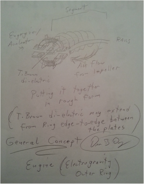
I can guarantee the Outer Ring will be in either one configuration or the other!
Both have a di-electric through the diameter that is not shown, if used specifically for the Outer Ring, instead of to generate negative energy. This is a possibility of two different configurations, one in which the flow from the vertical core impeller flows in only one direction (vortex) around the perimeter, and in another where the flow is divided into two opposing co-counter flows around the perimeter.
This has been bugging me for days.
I think the only way to determine the difference is to build it and test it. In the right image, there is a polarity through the diameter where there is definitely say a positive on top and a negative on the bottom which can polarize the Townsend Brown di-electric through the center. It is in fact, the right image which is similar to the style of exotic energy and negative energy generation using a special proprietary method.
This is the entire reason I wrote this article.
One way or another, exotic energy is generated as per the article just below this describes, in a collision of positive and negative, essentially unifying the flow of matter/energy at that exotic state of matter/energy near-unity (described as a "light-drive").
I am very inclined to state that the right image is the correct configuration; and if that is so, then it changes the overall physics in general to be used in the hyperdrive / warp drive starship, no longer depending upon the mass of particle flow to be cancelled in the outer ring, but directed in vortex to achieve a matter/energy unification in the diameter rather than a cancellation. It is the Unity of matter which creates Light, and so it is most logical to conclude that it is the right image configuration that will work. However, it is important to understand the difference overall between the two, because there are different styles of hyperdrive / warp drive engines that can be created.
As long as the physics are understood, then there can be multiple ways to achieve interstellar FTL (faster-than-light) travel, while still being able to have a working unified physics to explain the entirety of what CAN be achieved.
~.~.~.~.
One more thing to add:
There are coils, and there are plates, and sets of plates. Coils work with electromagnetic transverse energies, except for bare-wire coils working with di-electric parallel energies along with electromagnetic energies. Plates work with di-electric parallel longitudinal energies, which are electrostatic. Those are the two fundamental dynamics of electro-mechanical and radiant-electrical power generation and gravitational engineering.
Two sets of plates will accumulate a longitudinal parallel energy charge. You can obtain a polarity from separating two sets of plates over a distance, because the polarity will be formed by separation through a span of distance, in a frequency of time. Even though the surface charge of Earth ground is a positive, if you put one electrode of a digital voltmeter into one spot on the ground, and separate the other electrode to another spot on the ground, there will be a measurable flow of current with polarity. Bada-bing, bada-boom. Simple.
The trick is how to build it in an engine, or a generator, and how to transform those energies into usable current, and in either positive MAGNETO-ELECTROSTATIC ENERGY, or negative, and where to place them within a configuration (typically, magneto-electrostatic energy in this application is going to be negative energy, due to its derivative from an electromagnetic collapse).
Coils and plates can work together as well, for example as seen on the Tesla Engineering Physics page.
This is a phenomenal new direction of physics and engineering than what the world knows. It is very efficient and simple ultimately. It does take a LOOOOONG time to understand.
This website though shows pretty much EXACTLY how a hyperdrive / warp-drive starship would be built.
This design is actually held by the LAU Trust. I can't claim credit all of my own.
Don't let that electromagnetic coil winding throw you off into confusion. The energy from the coils can be collapsed and oscillated, OR the energy running through the coils can already be from a spark collapse coming from auxiliary generators in the wing edges. Those are also two further possibilities. As with most motors, they can also be made into generators, which would make the Outer Ring into a potent exotic generator for hull plating and air-flow guides through the in-between inner and outer hull spaces.
I like the concept of the Outer Ring working in tandem with the Vertical Core Impeller. But magnetic orientation may very well give way to di-electric polarization, due to the inclusion of Townsend Brown's electrogravity technology of the 1930's, which would make this ring segment oriented as shown.
The charged air flow from the vertical core could very easily provide power wirelessly to the Outer Ring, where it builds up energy due to back-and-forth electromagnetic collapse in AC. The ring segment is a self-generating system requiring just a little bit of power input. Separate mechanical timing systems can be used to pulse each coil, as in the OTC-X1 system, keeping it analogue, if one prefers.
This is as much detail as I am prepared to share, at this time. The vertical core and OTC-X1 are easy compared to this system, which is as good as it's going to get without additional funding and team-members to further this development, which might get expensive.
The Outer Ring is not supposed to be a heavy massive system due to the relatively small size of the vertical core. This system correlates the overall field, and enables a mass/energy unification field around the ship to augment the gravity/inertial force of the vertical core along with the gravity cancellation system of the OTC-X1.
I do not think you will understand this system unless you also read the article(s) below, and articles on the General Blog, Tesla/Free Energy page, Updates and Design Improvement page, and the Tesla Engineering Physics page, and the Warp Drive Engineering page. This engine architecture is also known only to the few. I had expressed my intention to explain the physics so people can understand it. But this as far as I can go before I overstep my original intention that got me this far.
My goal is to show that this is real and possible, but it is not entirely my specific field to show the actual engines / generators in action, which as I have said many times have actually been created and demonstrated in private. It would be great if someone wanted to fund the construction of a warp drive starship. But until that time comes, and/or more people come out with their own achievements, warp drive is only as real as willing investors.
It was suggested by a German inventor / researcher, to use an asymmetrical generator. And this is what we have. Note the axis of X and Y.
I am crossing the line by adding the above image. I just realize that it's very unlikely for anyone to ever discover it, unless they have specifically been taught by Tesla himself, or his partner. So ... Please forgive me ... I just do not want this knowledge to be lost. It's vague enough at least. Some aspects are slightly off ... I'm sorry, I just can't. ... This style belonged to Tesla, and his partner Cal, and has been passed along, and truly is not mine to give. It belongs to another, who is afraid to come out. This is a poor representation but it GIVES US SOMETHING. ...
Not only does the Outer Ring generate power, it can transform the energy throughout the ring into very high frequency/voltage.
There would be no need for separate transformers housed in the saucer-wing spaces which could be utilized for other things.
. . . Also recall the Outer Ring accelerates the particle flow; however in the article below, it discusses unifying that energy of particle flow.
That should be handled through the di-electric medium, a zero point between di-electric longitudinal waves AND transverse electromagnetic waves. Light is a magneto-electrostatic unity. See the Free energy / Tesla page, the article titled "Tesla Power." It is not cancellation in this case, it's unification.
When dealing with exotic energy, we are dealing with unity energy, and an enormous power output.
There's an article about exotic matter on the warp drive blog page.
Brief note upon alignment of charge in a particle flow: An electric current running along a wire will have an electromagnetic spin. A proton flow will also have an electromagnetic spin, in the direction of its motion. A positive flow will spin say clockwise (I'd have to look that up to be sure), a negative flow counter-clockwise. That applies to either an electron flow along a wire, or a proton flow through an air core, and determines polarity of the currents (see the above images).
Using the ring segment design on the Free Energy / Tesla page, or even on the above images, there is a left flow and a right flow along the central di-electric, or a clockwise flow and counter-clockwise flow in the same direction through the central di-electric, but opposite spins on the top and bottom hemispheres. What we are seeing then, is the distinctiveness of the polarity of the top hemisphere and bottom hemisphere, which is also why the di-electric plates terminate in the center (See the Free Energy / Tesla page for that image, in the top article, "Tesla Power.") . . . sorry if I don't post that image here, but it defeats the point of having separate pages. One of those purposes for separation is to enhance one's understanding through categorization and compartmentalization, requiring mental organization, determination and focus to follow along . . .
Timing of the "A and B" aspects of the individual Tesla energizers (to induce resonance), and overall ring hemispheres, and accelerator frequencies can be achieved mechanically through a rotating "points" distributor-style system. To be clear, an accelerating waveform through the two ring hemispheres (upper and lower accelerator frames) might require two separate distributor electrical timing systems. ... Nothing special about that, it is a given that timing is required. It should be fairly self-explanatory. The top part of the sine wave moves clockwise, the bottom counter-clockwise, or vice-versa. An accelerator tends to work specifically. ... I added this last paragraph as an after-thought, just in case.
You should get the idea . . .
 RSS Feed