NOW UPDATED: Explanation on How It Works, below in PART V
Rotating and counter-rotating charges antigravity demonostrated in Russia with an un-identified (update: now it's identified) metallic alloy.
Please check out the research of Alexey Chekurkov, who created the Alex Flying Craft.
Special thanks to Walter Nowosad for sharing this.
Rotating and counter-rotating charges antigravity demonostrated in Russia with an un-identified (update: now it's identified) metallic alloy.
Please check out the research of Alexey Chekurkov, who created the Alex Flying Craft.
Special thanks to Walter Nowosad for sharing this.
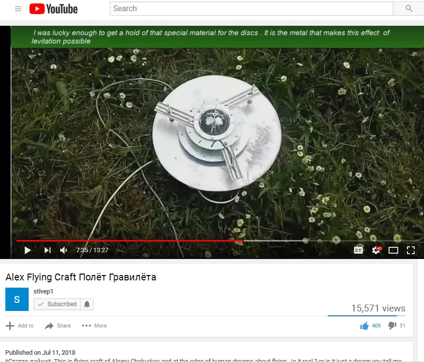
"Special Metal" is unknown. It looks like hammered tin, or an aluminum/bismuth alloy, hand-forged. It looks coated; plated, and easy to machine. It is known that the disks may become magnetized, meaning it is a ferrous alloy. It won't work when the disks are magnetized, probably causing a problem with spinning, or otherwise electrical disruption due to homopolar motor effects back-feeding into the external high voltage power supply.
He does have a lot of that metal on hand, however. He has made other apparatus from that metal, as per links below. It resembles an iron / tin allow for corrugated roofs with perhaps, a galvanized zinc plating.
It would most probably be a standard type of easily-acquirable metal.
Also note the power supply in the video below, using a Tesla resonance transformer. His standard power supplies however are using "positive energy," rather; whereas these metal disks are essentially rotating air capacitors. Being able to conduct magneto-electrostatic fields and usage of the Tesla resonance transformer denote that they are charged as a field at high volts, using non-standard electromagnetic (positive) energy; and the electromagnetic energy from the transformers would be going toward powering the motors that spin the disks, not using homopolar motor technology.
Note the blending of the energies of magneto-electrostatic and electromagnetic in high volts.
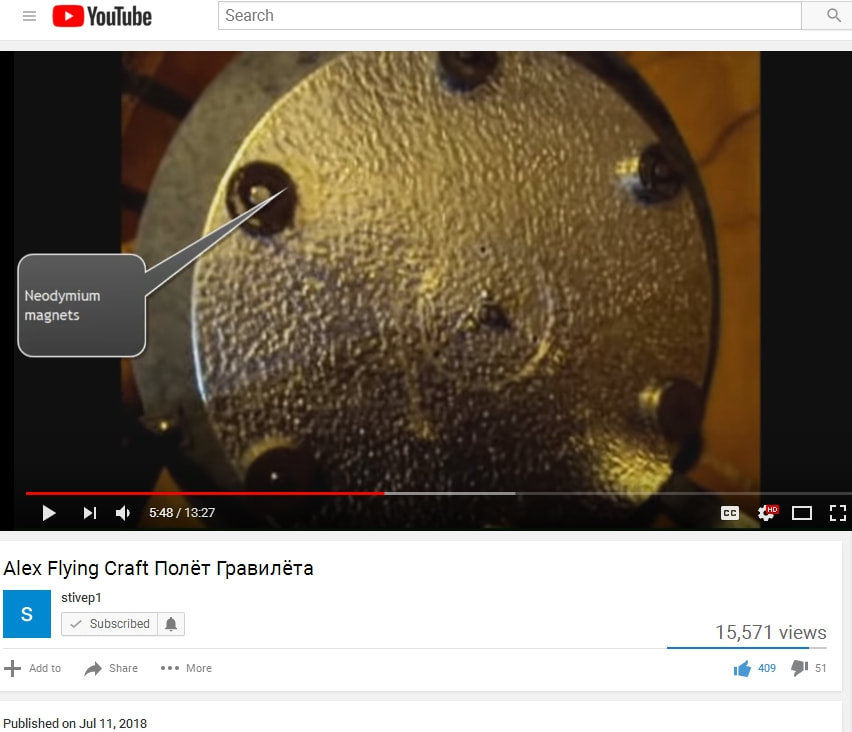
Furthermore, he uses neodymium magnets in the positions of the utrons near the outsides of his lower disk. The magnetic field near the outside while spinning them, denotes the electromagnetic collapse of magnetism toward the center -- in that field geometry.
This begs the question of the utrons being magnetic, whereas the outer electromagnets of the X1 collapse somehow in timing with the passing utrons, and a coil around the utrons could be built to handle that collapsed energy in polarity opposite of the utron-magnet, to deaden or cancel the utron's magnetic field in order to pass through the electromagnetic gate.
Aside from that complex structure, a homopolar motor design with electrostatic rotating disks may actually be able to handle rotating magnets spinning in the opposite direction of one of two counter-rotating field disks; it seems that the rotating magnetic fields are only traveling in one direction.
It's easy to see the device comprised of two capacitor sets, one on top (with lower rotating disk), and one on the bottom, with lower rotating disk with magnets. He is NOT using homopolar motor technology, and he's using an external Tesla coil power supply, instead of integrating that into his design, although it is using a conductive hollow "hat" similar to a Tesla tower. Also note the static disk, rather the disk that is not moving, with the frame "landing legs" sticking through it.
Note the bottom rotating disk is wider than the upper rotating disk, keeping to principles of the magnet and dielectric layers, using a wider magnet on bottom and on upper magnet, in less width, in adherence with the Townsend Brown in a vacuum test shown on the pdf file on the Construction page in the Townsend Brown section.
He does have a lot of that metal on hand, however. He has made other apparatus from that metal, as per links below. It resembles an iron / tin allow for corrugated roofs with perhaps, a galvanized zinc plating.
It would most probably be a standard type of easily-acquirable metal.
Also note the power supply in the video below, using a Tesla resonance transformer. His standard power supplies however are using "positive energy," rather; whereas these metal disks are essentially rotating air capacitors. Being able to conduct magneto-electrostatic fields and usage of the Tesla resonance transformer denote that they are charged as a field at high volts, using non-standard electromagnetic (positive) energy; and the electromagnetic energy from the transformers would be going toward powering the motors that spin the disks, not using homopolar motor technology.
Note the blending of the energies of magneto-electrostatic and electromagnetic in high volts.
Furthermore, he uses neodymium magnets in the positions of the utrons near the outsides of his lower disk. The magnetic field near the outside while spinning them, denotes the electromagnetic collapse of magnetism toward the center -- in that field geometry.
This begs the question of the utrons being magnetic, whereas the outer electromagnets of the X1 collapse somehow in timing with the passing utrons, and a coil around the utrons could be built to handle that collapsed energy in polarity opposite of the utron-magnet, to deaden or cancel the utron's magnetic field in order to pass through the electromagnetic gate.
Aside from that complex structure, a homopolar motor design with electrostatic rotating disks may actually be able to handle rotating magnets spinning in the opposite direction of one of two counter-rotating field disks; it seems that the rotating magnetic fields are only traveling in one direction.
It's easy to see the device comprised of two capacitor sets, one on top (with lower rotating disk), and one on the bottom, with lower rotating disk with magnets. He is NOT using homopolar motor technology, and he's using an external Tesla coil power supply, instead of integrating that into his design, although it is using a conductive hollow "hat" similar to a Tesla tower. Also note the static disk, rather the disk that is not moving, with the frame "landing legs" sticking through it.
Note the bottom rotating disk is wider than the upper rotating disk, keeping to principles of the magnet and dielectric layers, using a wider magnet on bottom and on upper magnet, in less width, in adherence with the Townsend Brown in a vacuum test shown on the pdf file on the Construction page in the Townsend Brown section.
Part of it is powered through a Tesla resonance coil.
Here are some of Alexey's comments:
"A new lightening disk was made and a video was shot. But someone influential complained and yutub blocked the roller. But one user managed to download and reapply but again called feykovy flight. He decided that if the terminal with akamulyatora removed means fake. But I explained that from time to time you need to remove the power from the TDX to prevent the magnetization of the disks and prevent the subsidence of the parameters. If you have not seen the movie, I'll throw the link."
Here, we see the same metal on this video, which is not a YouTube video:
https://thexvid.com/video/_LZ0-dQxKwI/%D0%B1%D0%BB%D0%BE%D0%BA-%D0%BF%D0%B0%D0%BD%D0%B5%D0%BB%D0%B8-%D0%B3%D1%80%D0%B5%D0%B1%D0%B5%D0%BD%D0%BD%D0%B8%D0%BA%D0%BE%D0%B2%D0%B0-%D1%82%D0%B5%D1%81%D1%82%D0%B8%D1%80%D0%BE%D0%B2%D0%B0%D0%BD%D0%B8%D0%B5.html
Okay, here's the YouTube video of the above link:
Notice how those can resemble OTC-X1 central rotating disk segments ??? Check out the cheat sheet on the article below . . .
Following his research, you can see more about the field flows here:
AND ... BAM! Found the type of metal he's using:
"This corrugated aluminum with an anodized coating structure similar to the beetle fenders. So successfully coincided."
Guess I need to mention Alexey mentioned in a comment on one of his bug wing videos what the material is -- the anodized corrugated aluminum. I spent hours translating Russian into English and searching.
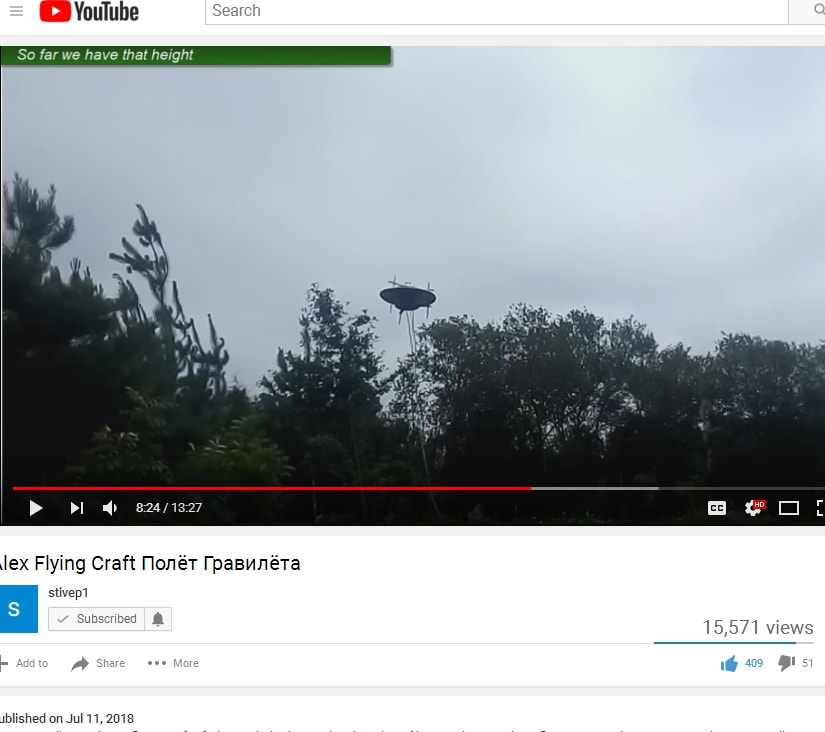
This represents the first successful testing of the rotating and counter-rotating charge antigravity craft, able to lift a considerable amount of weight, and when applied in an air-tight resonance cavity hull may also work in a vacuum.
So now we know that the rotating and counter-rotating charge principle of physics DOES WORK.
PART II
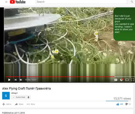
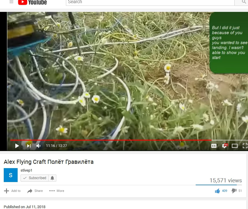
I want to take some still-shots of the videos, and notes, to have a photo reference, just in case, because Alexey mentioned that his prior videos were removed from YouTube in order to suppress the technology.
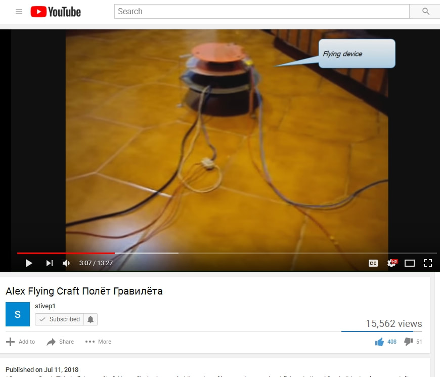
He uses modified high voltage power supply from switching power supply for his original test. The first disk is powered up using a standard motor, plugged into a wall socket (power strip) which gets it to spin, as is the second disk. The disks are mounted to stationary frame (stationary disk), which the two motors are bolted to. The disks are arranged as capacitors, so the presence of unmoving disks in the engine will not cause it not to work.
After the two disks (the one on the very bottom, and the second one from the top) are spinning in opposite directions, most definitely. You can adjust your video settings for high quality to see better. The next step is to connect the high voltage power supply (after all, as I've said before, all forms of electrogravity use high voltage). In the OTC-X1, that is achieved through high volt flyback from the electromagnets.
Okay. The high voltage is plugged into the stationary disks by the looks of things, and the rotating disks picks up one polarity of the dielectric charges, but both stationary disks are on top of the rotating disks, so the orientation typically used is positive up and negative on bottom. If using positive on the bottom, it would be repulsive to the Earth surface charge, and not achieve significant height, in my opinion.
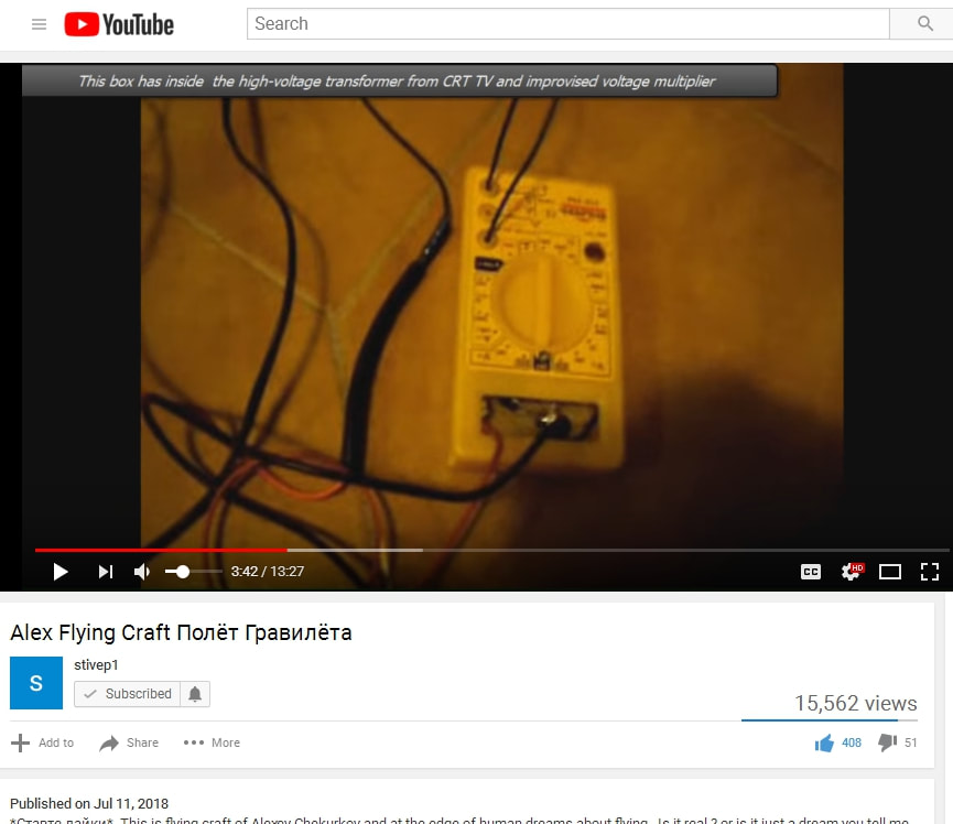
The orientation of negative on bottom and positive on top effectively means that the co-counter-rotating disks are spinning positive against negative, looking at this in the form of capacitor geometry. His high voltage source is the typical high voltage transformer from a CRT tube and improvised voltage multiplier (positive energy high volts, just like most people do with their electrostatic lifters). You can hear the zzzzzaping when he plugs in the voltage multiplier.
High voltage supply is the box in the middle photo. Multiplier is the hand-held device on the floor in the right photo.

He says the high voltage performs the "magnetization of sectors." It's in Russian, but there is an English translation.
Voltage and speed (inertial frequency).
The bottom left is levitating. Bottom middle is side profile. Bottom right is the bottom of the engine, and those are the 6 neodymium magnets.


PART III
Okay so here is the successful test model version 2.
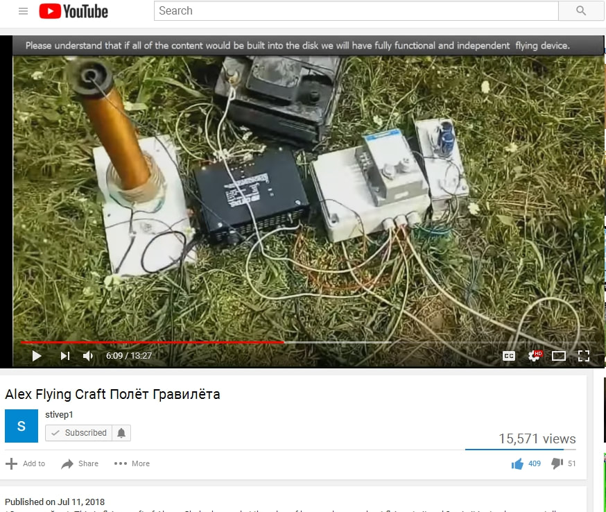
The mess on the left is the power supply. Tesla resonance transformer, and immediately to its right is the power supply for it. The box on the far right is the independent power supply for the transformer block, and the little white box on top of the big white box is the high volt power supply. It's all connected to the 12 volt battery. I'm recording this for posterity, just in case.
Alexey continues to explain that a conflict of sequences steps caused his previous model to fall down, and he has to do a lot of fancy adjustments to get the craft to go up in the air, and sometimes it may take 30 minutes to balance everything correctly. Basically he explains that his power supply system has to be charged up in a certain order, probably due to resonance, like how a capacitor has to be charged first in a basic LC circuit (see the article below), and then when resonance starts to break down, he needs to provide an input to the capacitors, but it ends up going to the wrong place (the transformer instead of the capacitors), and his high voltage signal starts to degrade.
I don't want to speculate here too much about his power system, though. Not yet.
The second device, his working prototype is impressive, and obviously upgraded from the first, yet still having the same overall characteristics, and using better field geometry.
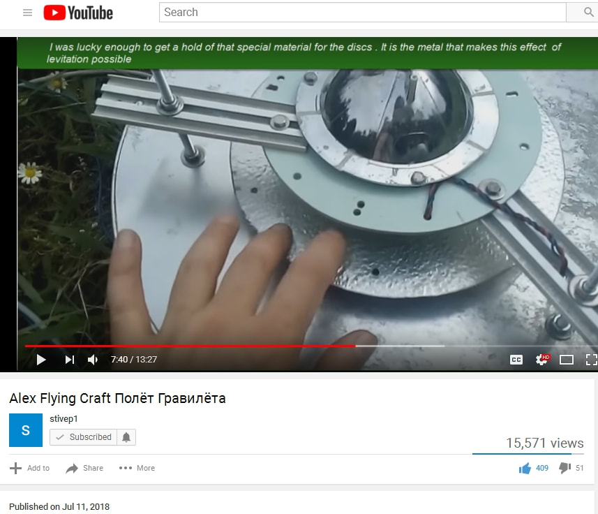
We know now that he is using corrugated aluminum with an anodized coating, which was the same material he used for the CSE beetle (sound resonance cavity) experiments, from the Russian etymologist years ago who discovered that effect. The piece he is touching is the upper rotating disk. This is awesome! It's like a TR-3B engine (1 of 3 on the triangular hull's tips). Just think how this style can be adopted to use a homopolar motor design instead of dipole standard electric motors.
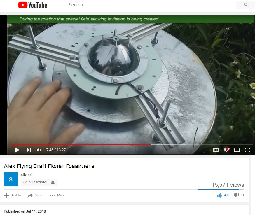
Here below is a better view of the whole top. The special field is theorized in different ways. One theory is a positive and negative electrical mass cancellation. Otherwise it's not very well known how it works to be honest. If you consider electromagnetic spin reverses on either side, up and down, left and right within orientation to electric fields relative to a plane of gravity, then the spin one way and spin the other way seems to cancel gravity, along the middle and much wider disk plane.
Magnets are involved, however. In fact, the article below this one showing the little diagram of the outer electromagnets in homopolar motor configuration spinning two disks in opposite directions is similar but I REALLY LOVE the concept of the centralized wider disk in Alexey's application. Similar to magneto-electrostatic, or just static electricity with the two counter-rotating disks creating electrostatic friction on the central wide disk. The two rotating disks appear similar in size.
If you notice also where the high volt top disk is, it is connected via frame to the central disk, but later on it shows Alexey touching the legs of the device during levitation, and touching the bottom middle.
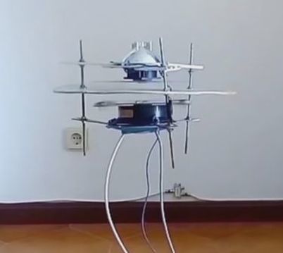
He uses three wires: one high volt from the Tesla resonance transformer, and two wires from the rotating disks. I would say he is using a homopolar motor design in this version, due to only two wires to handle the rotating disks, and the third as the high volt magneto-electrostatic feed.

. . .
Here is the best profile shot I could capture. You can see the wide disk, landing struts (frame), a tiny sliver of the top rotor disk, and the bottom rotor disk.
Note also in the bottom photos, a contact strip from the legs reaching out to touch the rotating bottom disk area, probably to transfer the charge, as a brush.
It does not look like there are magnets on the bottom of the disk, though.
Note also in the bottom photos, a contact strip from the legs reaching out to touch the rotating bottom disk area, probably to transfer the charge, as a brush.
It does not look like there are magnets on the bottom of the disk, though.
It looks like the magnet is above the lower disk, and if you think about a homopolar motor, then it would seem to act in just that way.


So there you have it!
Different styles and designs. Makes me wonder about the OTC-X1 now -- counter-rotating electromagnetic field versus counter-rotating electrostatic disk.
Make sure you click on the images to magnify them and see the whole image.
PART IV
So we have a successful flight test, on two occasions (original model and remake), which looks fairly legitimate; and although Alexey didn't get his camera up close to his craft as it was levitating so we could get a really good super close inspection of it (he may be wanting to keep some proprietary secrets, who knows), at the very least it is demonstrating a familiar geometry:
A rotating electrostatic disk, in counter rotation to a rotating magnetic and electric disk. The lower disk is separating the magnetic and the electric aspects (rotating magnetic field, coinciding with a rotating electrostatic field) in BOTH designs of his. The upper disk remains a constant variable, but the shape of the engine itself has changed (which is okay).
His power system is many times larger than his test craft. The OTC-X1 however includes a potentially self-contained power system in its design, which is why we favor the OTC-X1 for the ultimate craft, yet engines like Alexey's are favored in the testing phase to understand the physics and the power systems.
Yet, we still need to understand how the OTC-X1 works, and Alexey's design is a practical application toward achieving this goal.
From the articles below, we can see how all these systems co-relate, and there is a pattern:
Counter-rotation of electromagnetic and electrostatic rings / disks. There must be a magnet involved, and there must be electrostatic involved, and high voltage, but we can simplify the energy requirements using flyback from the collapse of the electromagnetic coils, while also using those electromagnetic coils as our rotating magnets. After all, a homopolar motor will work in many combinations, in both two-piece and one-piece dynamics.
The utrons also double as rotating magnets, and static field generators. The utrons are in the same place as Alexey's original experimental device, 6 of them around the perimeter, but are oriented along the 45 degree inclination / intercept; and we have some comfortable spacing in between the OTC-X1 components for timing the engine pulses and collapses.
The OTC-X1 blends Searl and Alexey Chekurkov designs.
I would like to open up the Comments field at this point, to gain some much-needed feedback from others about any ideas and discoveries and tests that can be brought to the table of our common goals.
I want to hit some basic highlights however, just to make it easier for the newbies to do a search on.
Highlights:
1) There has to be a magnet to get the device to spin, but the unifying principle seems to be co-counter-rotating electrostatic high voltage disks. (although rotating electromagnetic fields can be intrinsic)
Sources of high voltage:
Capacitance and flyback (utron kinda remind me of doornob capacitors). Utrons act as high volt capacitors.
Don't discount the central accumulator from being able to store high volt capacitance from the flyback. It's strange gotta admit. Capacitance would help raise frequency otherwise there would be a pulsed mechanical frequency that needs to be raised thru resonance and capacitance.
2) I mentioned i'm going to use an induction coil for some tests.. and I got to thinking one big coil could equal a bunch of smaller coils but would still need capacitance to equal what one big coil can do.
3) It would not be a stretch at this point to consider the OTC-X1 as a flying induction coil. If you eliminate the complex scalar warp drive physics and just stick to engineering, one could make better sense of all this mess from doing some creative experiments.
The one noteworthy thing about the utron / accumulator 45 degree cone shapes tho is the intersection of parallel / longitudinal electric and transverse magnetic fields. THAT is probably the ONLY reason they are significant.
4) THAT is what scalar energy is about. Actually no that's what NEGATIVE energy is about. Without that component there's no guarantee it will warp time ... and furthermore cones within cones may make a better crystal power cell electret material alignment in the central accumulator than flat plates in the accumulator.
That means there will be a mini utron-shaped hollow cavity inside the central accumulator.
That also might be the reason the X1 is able to hold its own self-regenerating overunity power system.
Each interior cone segment can have individual electret "sticks" arranged in cone shape too, basically sub-dividing each cone section so the electret material can be better electrified/magnetized.
5) This from Matt Tracy ... in regard to Bismuth and Aluminum alloy in Roswell crash - Arts parts:
"Now I do know that both bismuth and aluminum are paramagnetic. And i also know that bismuth has two very interesting qualities to say the least. Bismuth when flattened to 5-microns or less becomes naturally superconductive at room temperature. Bismuth's second amazing quality is that it is naturally at the atomic scale has an asymmetrical atomic geometry. And we know that it requires asymmetry in the dielectric field to produce a counter wave to asymmetrical dielectric fractal emission that we we ignorantly call gravity."
Aluminum anodized with bismuth is a good idea. I also know of bismuth becoming superconductive in small slivers. Graphite too has similar properties in thin wafers. Diamagnetic or something if memory serves. Able to reflect the magnetic field perfectly to hover a magnet over it.
UPDATE: there is no need for bismuth since a rotating aluminum disk acts diamagnetically upon a magnet, reflecting the magnet's poles.
6) Also ... just because a system may be generating negative energy, it does NOT mean a system is reducing mass, and suddenly a large craft has nill inertia. These are specific fields and the only way to explain them is to show their relationship with action.
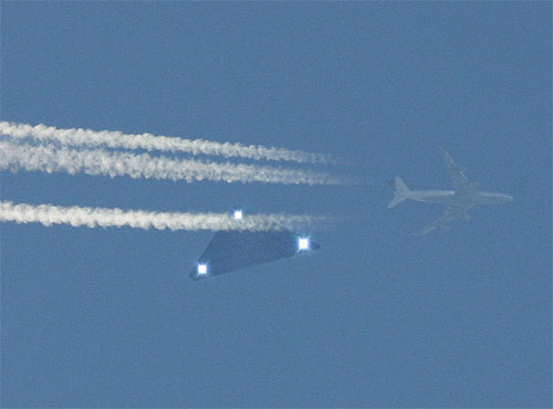
If something has no inertia, that is a local field effect and due to a field effect. By now, everyone knows how UFO and TR-3B craft move in their sudden accelerations and right angled turns that don't squish the pilots.
But an electromagnetic field collapse does not make the coil weigh less; but if that force can be harnessed in scalar ways in high frequency, in a perpetual energy of collapse without it filling up, and thus increasing energy output, THEN it's something.
And even tho Stephen Hawking says the total energy of the universe is zero due to negative and positive energy, it does not mean that negative energy is the absence of energy. That is a dumbass assumption.
And I really apologize to those still stuck thinking that opposing fields cancel mass when opposing fields only cancel energy output to zero and they're not even able to get a basic generator to work because they wind their coils in opposition. I don't know what to tell those people who absolutely lack and practical experience and have never wound a coil in their life.
I'm just very careful not to call flyback voltage negative energy, because if it's not overunity, it's not necessarily negative energy. It may have its BASIS in the collapse of an electromagnetic field, BUT it's more complex than that. I recommend reading the website to gain an understanding of it. Some of you absolutely refuse to read the website because you have to READ it, and instead find it easier to peg me with a whole lot of questions that take up my time to be building stuff.
And technically speaking, it's not negative energy that provides the whopping load of voltage, but with very tiny amps. You can GET amps out of it though, which is a complex manner to do so, requiring secondary effects. Negative energy provides amplification, overunity, and in additional configuration mass reduction, but that additional configuration is a complex system that is only theory right now until we can measure it against a clock.
ADDITIONALLY: Apparently the TR-3B is canceling out inertia and gravity and increasing the frequency of time ONLY and JUST THROUGH THE MECHANISM of running high voltage along its hull ... and there's NO NEGATIVE ENERGY INVOLVED WHATSOEVER! ...... This can be used in space then packing the air along with the craft in double-hull configuration, in circulation fields.
As the Alex Flying Craft shows, there is not an ion wind effect of lift as a thrust, because the engine is not designed to use that principle! It's demonstrating come kind of static lift but, not ionic thrust. These physics could just be completely simplified at this point, and go back to how it was on the Warp Drive Engineering page which never once got into negative energy, and only dealt with high volts. I am however convinced that there is a special secret with negative energy, in that an overunity power supply as well as high volts can be obtained through a MUCH smaller generator deriving energy from the electromagnetic collapse.
For those who don't know what a "TR-3B" is, here are some photos:

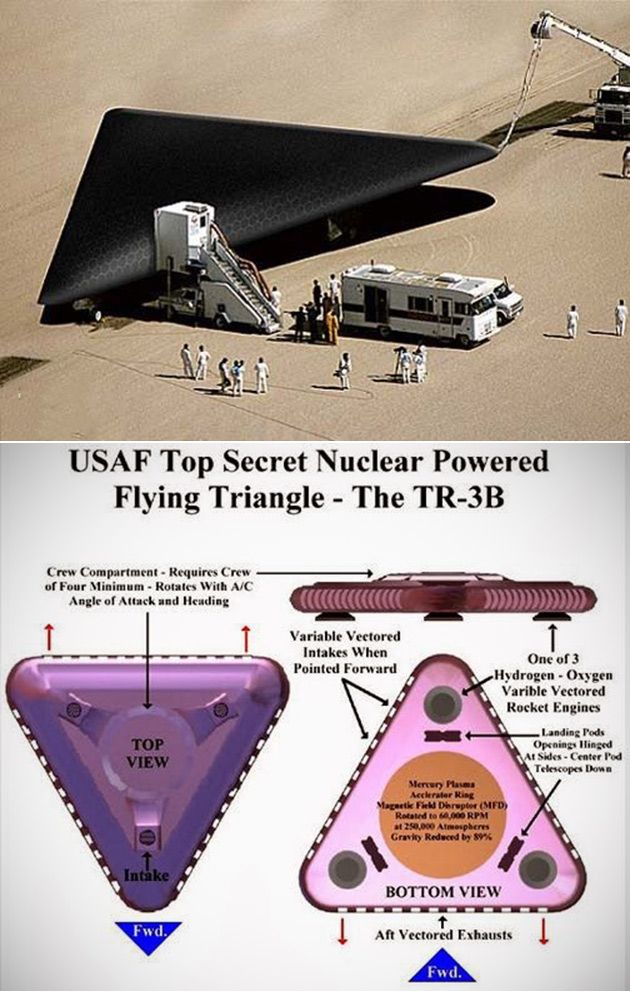


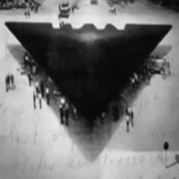
7) And finally regarding spin... a photon has spin of one whole whereas matter has spin of 1/2. The addition of -1/2 + 1/2 is not zero, but is a 1. Matter and antimatter combine as light, not as zero (as void) as Stephen Hawking would have us believe. (he said the total energy of the universe is zero due to positive and negative energy)
This is why magneto-electrostatic spin and counter-spin cancel inertial mass. Light does not take time to travel; it is a static field throughout All. Only matter experiences time.
8) Regarding negative gravitation:
According to the TR-3B patent (https://patents.google.com/patent/US20060145019A1/en), electron inertia moves forward on the ship, pulling the ship along with it, creating a gravitational force of moving electrons, moving in parallel to the inertia of the moving electron mass. FREQUENCY SEEMS TO BE THE MOST IMPORTANT FACTOR, when pertaining to electron mass, gravitation, and inertial VIBRATION (and polarity).
Negative gravitation as it pertains to the OTC-X1 very well may be throwing electrons out to the sides, creating a force of negative gravitation in the center, and positive gravity around the hull, negating the local gravity fields of star systems or planets in that polarity of active inertia.
As I stated in the article below, for some reason I had it in my head that the electrons gathered toward the Accumulator, creating a positive force of gravitation there which negated the gravity fields of surrounding local planets and star system fields. .... This needs to be noted.
At this point, I'm not seeing anything new come up; some people are suggesting the same things I've already suggested and discussed. We seem to be on the same page at least ..
At this point EVERYTHING has been taken into account regarding the OTC-X1 analysis and probabilities, and thoroughly discussed, so that the last step remains is to build it BECAUSE WE SEE due to the Alex Flying Craft, that THESE PRINCIPLES DO INDEED WORK!
It's time to build, and put it to the test to see what works, and what can work, and what doesn't do too well.
PART V
Theory Update from the Comments (peer consensus)
(I'm only including a few highlights, because a lot has been discussed, and the good parts unfortunately were not in the comments; but at least it's practical info):
--UPDATED--
It was explained to me that it is not real physics, unless there is either A) mathematics to explain it, or otherwise B) an explanation on how it works. ... It was also explained to me that it is not proof unless there is only mathematics, that a demonstration of a working device is NOT considered proof. <--- What's wrong with that picture?? Yes, someone REALLY told me that, and was quite fervent about it.
Sorry but a working device is proof of concept. Consider it the art of science.
Here's the explanation, AND the
Unifying Theory of the Creation of Gravitation:
Background of Tesla physics involving DC pulse:
DC pulse is only responsible for arresting the electrons from moving: pulsing the voltage, basically opening the circuit back up before the electrons has any time to gain momentum and begin moving (an electromagnetic field can collapse at light speed). Electrons are only good for creating losses, they absorb the energy being suddenly drawn in by the circuit from the surrounding environment. Electrons moving creates the heat in the circuit. That's why pulsed DC VOLTAGE (Impulse Flyback Waves) has no heat and no amps in the circuit -- only if harnessing flyback thru a spark gap. Otherwise an induction coil gets hot from the pumping electromagnet.
DC High Voltage is being pulsed at varying frequency (high or low), but the CURRENT is not being pushed.
-- The output can occur at the speed of light.
DC high volt pulses at high frequency impulse (wave characteristic), is the electrical aspect that aligns the quantum spin and energy forces in polarity without regard to mass (electron mass). This has an inversely proportional characteristic between energy, frequency, and mass.
Instead of harnessing electron mass, it is the harnessing of the frequency of electron (electrical) energy, as well as spin polarity, similar to Dr. Ning Li's "AC Gravity" device, which is now quite popular, and that concept is being used by other experimental physics groups and companies.
The similarity to her device is that the things that are spinning are not being allowed to move, but are locked in place (similar to the Bose-Einstein condensate), but the electrons are the things that are spinning at this point. The energy of their mass is directly transferred through spin, through the electromagnetic field (displacement of mass and energy).
It is seen that energy itself can move superconductively in the Eric Dollard experiments. If that energy displaces the electron mass, then as the energy reaches higher voltage and higher frequency, the amps can drop into the negative range -- the mass of the electrons (an electron is a paradoxical particle; not considered a physical object) drop to zero, because mass is not what is building up the energy.
. . .
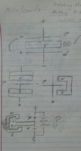
"A homopolar motor works because a one charge is placed on the paramagnetic disc. One thing you need to change in your understanding of charges is that all electrical charges is nothing more then spin. All positive charges spin in one direction while all negative charges spin in the opposite direction. It's all about spin and spin direction.
If it is so that two counter rotating dielectric fields are required to achieve electro-gravitic flight, then from a scientific standpoint point that which we call gravity must be a dielectric field effect. Otherwise a dielectric field should have no effect on gravity if there is no fundamental connection between the supposed two forces. In all described electro-gravitic craft, there is a dance between two separate fields -- one rotating in a counter direction to the other." [This can be seen as the proton spin of positive charge and the electron spin of negative charge, whereas changing the spin frequency and voltage of the protons and electrons in the material of the rotating disk is caused by induction]
"When the field that is rotating in the same direction as the earth's field, it is stronger then the opposing field, IE negative on negative, the ship is repelled away from the earth's surface. When the field that rotates counter to the earth's dielectric field is stronger, IE positive field, the craft is pulled towards the surface of the earth. The difference between these two counter rotating fields allow us to control the ship's altitude and at what rate of speed the ship achieves that altitude. So it stands to reason that the force that we erroneously refer to as gravity must be nothing more the a dielectric field effect occurring between two counter rotating fields."
-- quantum spin polarity is "rotation" in this case, and yet a physical rotation on the disk must also and therefore be present, if the quantum universe truly represents the physical universe of motion, inertia, frequency, energy, and spin, etc. This is to say that "macro" and "micro" realities are not backwards from each other as quantum mechanics appears to be, but is instead not involving mass -- the very thing that is relevant to gravity, time, and the speed of light.
Most physicists will say "oh, that's hogwash; that cannot exist." I've heard it said for 20 years, and after a point, you tend to want to go along with the crowd, YET CLEARLY this exists due to the Alex Flying Device, as well as Dr. Ning Li's device (now duplicated by other labs) -- quantum reality can exist unified in the micro AND macro reality through a unification of frequency (of time as that which is not source, but is the prime energy of the universe).
The outward dielectric and magnetic waves by the nature of their movement thru time, they create a counter polarity - a return wave through counter-space as you put it, which when that wave is harnessed, then the two flows can adjust the entire "reality" of that body of lets call it: gravitational capacitance - the gravity-time zone of our star system from Earth point of view.
How this applies: The two charged disks rotate at particular set speeds to create a standing-wave frequency which sets the "time flow" between di-electric spins (in angular alignment); the standing wave frequency is the frequency of time, which is a radiant field. See how this then has an effect on mass and gravity?
Ok. And so that can be controlled by controlling the special electromagnetic energy of the two disks OR of the one disk with outer counter-electromagnetic spin of the electromagnets.
That controls "gravity-time" ... in a negative electromagnetic field.
~.~.~.~.~.~.~.~.~.~.~.~.~.~
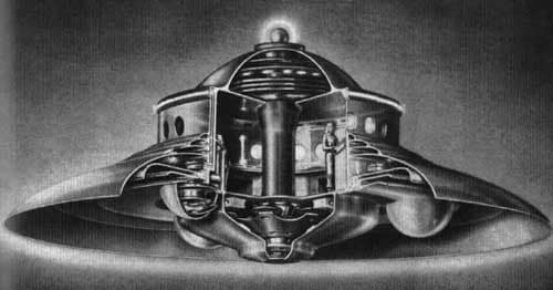
Here is a rather well-seen image these days
This is the design style of the Haunebu II
Here is a rather well-seen image these days
This is the design style of the Haunebu II
Things to note:
Spinning disks with magnets also spinning . . . a big resonance coil through the middle ... The bottom is generating power .. similar to the OTC-X1 ... And then there are capacitor layers in the hull.
Flight control pods underneath, which would make it much easier to control than how Alexey made his two-disk device.
This also includes Townsend Brown's (Bifeld-Brown) effect (Can use electret di-electric material) in the case of the non-spinning disks. Regardless and also, the spin polarity of electron mass displacement (contained in lattice) through rotating disks, and the static disk sections around the hull.
Also ceramic / magnetic layers can be used for a dielectric insulator.
Lateral movement is suggested to apply a high volt charge from center of hull / disk layers to the outside perimeter of the hull edge, in the direction one wishes to travel.
Radiation Shielding:
A brief note here. At having zero inertia, no resistance to motion, and no reaction to other nearby gravitational and acceleration forces, which is equivalent to having zero mass, it is the paradox of having a LOT of mass to shield from radiation.
At high frequency and high voltage, a hull within a zero inertial/mass gravitation field would not give radioactive static currents (high frequency ray energy having inertia)* any mass with which to energetically interact; and an electrified hull should be able to shield from high frequency rays -- a high frequency negative energy Faraday cage.
*Static current is not a duality, it is a paradox and so in opposition to itself, it unifies as a higher form basically, instead of negating its own existence. For example as high voltage is pulsed through an open circuit (capacitor plates, spark gap, etc), then this can preserve a type of static buildup throughout the entire conductive and working field generators (coils, capacitor plates, spark gaps, etc).
The voltage will flow, as it takes a moment to charge any system, and so the voltage fills out the spaces as it moves, but it is not considered current. Voltage jumps or voltage potential increases can mitigate its wave-forms (longitudinal or electromagnetic) traveling faster than what resistance is provided in a current.
... Regarding the concept of inertia, even light has inertia through timelines; having an inertia to manifest into the universe; reality has the inertia to move forward through seeming continuity. Inertia unifies ultimately even at the level of consciousness having inertia to act, and each action carries with it the inertia of purpose.
There is much about light that is involved here.
Furthermore, electro-inertia is different from electro-gravitation. Electro-gravitation involves the frequencies of time within a gravitational field in that way, to create the gravity field. Electro-inertia is the impetus for inertial force, be it thrust or lift, and can withstand Newtonian scrutiny.
Within electro-gravitation, electro-inertia can be applied to move a craft around quickly, without having resistance to motion (inertia). An example of electro-inertia is the Bifeld-Brown effect. An example of electro-gravitation is the OTC-X1 and the Alex Flying Device.
PART VI
Follow Up:
Alexey Posts another video of his Flying Machine!
Here is another video of the Alex Flying machine in which a Russian colleague criticizes his engine, not realizing there are TWO DISKS that Counter-rotate ... and not understanding the nature of the resonance involved with Alexey's Tesla system as to why the craft falls suddenly, which forces Alexey to make ANOTHER VIDEO, showing him lift it off and ungracefully land it on his living room floor.
It's all in Russian, so skip around for the good parts.
You can tell it's a bit beat up from the hard landing last time. Adjust your video quality for best viewing.
Thank you, Alexey Chekurkov for making this and sharing it with the world, and for showing the side profile!
Brilliant idea to make the one disk as the accretion disk between the two smaller spinners.
Brilliant! Three wires!
There is some never-before-seen force involved here, and it's probably something akin to a Torsion Field.
Theory explaining it: above in Part V.
Brilliant idea to make the one disk as the accretion disk between the two smaller spinners.
Brilliant! Three wires!
There is some never-before-seen force involved here, and it's probably something akin to a Torsion Field.
Theory explaining it: above in Part V.
Once again, the comment section is open in this article for finalizing design specifications to gain some much-needed feedback from others about any ideas and discoveries and tests that can be brought to the table of our common goals.
I will add one more thing. The commenter below is correct about an ultra-sonic generator. Take a look at this and follow the link on the bottom of this article: https://www.warp-drive-physics.com/updates-and-design-improvements/biefeld-brown-electret-dielectric-and-some-logistics-for-development
And please forgive my rant about funding....
 RSS Feed