Updated: 2/9/16
The Spark of Life
This is a simple approach, I don't want to get overly complex with this.
As a resolution to the Life Force philosophy concerning a living energy component in the system, the engineering balks at it. The only easy way to do that would not be a permanent way. What is most Sacred is most Permanent. The Central Accumulator should use Power Cell Electrets primarily. For one thing, having a living electrolyte can decay, and that is a much worse energy to be around.
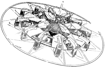
Here is a simple cutaway view to give you an idea. Regarding an utron however: An utron as a solid component of mass with a conductive non-magnetic surface and non-magnetic core is a better inertial generator. An utron picks up an electric charge in paradox to the motion of the electromagnets. This is required for "electro-gravitation."
Otis said they acted as the "batteries" that revolved around in motion, because he was dealing with a self-regenerating circuitry, not with a Central Accumulator as a permanent battery that never dies out.
However, using a Living Electrolyte, with alternating copper and zinc plates, the zinc would be consumed in the energy reaction, and I am unsure if self-re-energizing the battery would prevent that, but with a Spark Gap inside, it would become a Living Energy Battery.
There would be more power overall, would require the Accumulator to be separated into halves, and the Bedini Schoolgirl circuit would be the circuit that works. There are some interesting things about Utrons regarding their electrical capabilities when moved through electromagnetic field coils as the OTC-X1 Engineer teams have discovered. Also Carr said that the Utrons act as COILS (Bedini! Hint Hint).
Separating into halves is an easy thing, separated and affixed to the central rotating disk (accumulator frame), where the appropriate electric connections can be made (conductive strips and electrodes). The interior sphere can adjoin in nearly halves, where the accumulator frame (central disk) can make up that difference at the equator. It doesn't have to be a perfect, but the spark gap should be attempted PARTICULARLY when it is surrounded by a living energy eletrolyte such as fresh leaves and brown sugar mixed to a paste.
Actually, I wouldn't use sugar AT ALL. That does have destructive properties to the body's aura, which has been shown through science. I would use something different, if I were you.
A Living Electrolyte Energy would feel very good, I imagine, to those who have spent years living in Tesla fields!
THAT aspect of a Living Energy Battery is more worthy to build then a Power Cell Elecret Accumulator, and could be Life-Saving and Life-Regenerating. I would be a fool to just summarily discount that. Luckily, the wiring should not be all that different as described below, which all mainly pertains to a Power Cell Electret Accumulator, just to make things more interesting.
The design of the Accumulator "Reactor" below will not change, other than the plate material, and whatever considerations for dealing with the electrolyte without it seeping into the hollow sphere. You'll have the benefit of seeing two designs in one, somewhat at the same time (multidimensional article), and in somewhat of a comparison / contrast.
It won't spark itself. It has to be sparked by a high volt flyback charge from the apparatus it's connected into.
Here is a quick view just to give you an idea:
The Spark of Life
This is a simple approach, I don't want to get overly complex with this.
As a resolution to the Life Force philosophy concerning a living energy component in the system, the engineering balks at it. The only easy way to do that would not be a permanent way. What is most Sacred is most Permanent. The Central Accumulator should use Power Cell Electrets primarily. For one thing, having a living electrolyte can decay, and that is a much worse energy to be around.
Here is a simple cutaway view to give you an idea. Regarding an utron however: An utron as a solid component of mass with a conductive non-magnetic surface and non-magnetic core is a better inertial generator. An utron picks up an electric charge in paradox to the motion of the electromagnets. This is required for "electro-gravitation."
Otis said they acted as the "batteries" that revolved around in motion, because he was dealing with a self-regenerating circuitry, not with a Central Accumulator as a permanent battery that never dies out.
However, using a Living Electrolyte, with alternating copper and zinc plates, the zinc would be consumed in the energy reaction, and I am unsure if self-re-energizing the battery would prevent that, but with a Spark Gap inside, it would become a Living Energy Battery.
There would be more power overall, would require the Accumulator to be separated into halves, and the Bedini Schoolgirl circuit would be the circuit that works. There are some interesting things about Utrons regarding their electrical capabilities when moved through electromagnetic field coils as the OTC-X1 Engineer teams have discovered. Also Carr said that the Utrons act as COILS (Bedini! Hint Hint).
Separating into halves is an easy thing, separated and affixed to the central rotating disk (accumulator frame), where the appropriate electric connections can be made (conductive strips and electrodes). The interior sphere can adjoin in nearly halves, where the accumulator frame (central disk) can make up that difference at the equator. It doesn't have to be a perfect, but the spark gap should be attempted PARTICULARLY when it is surrounded by a living energy eletrolyte such as fresh leaves and brown sugar mixed to a paste.
Actually, I wouldn't use sugar AT ALL. That does have destructive properties to the body's aura, which has been shown through science. I would use something different, if I were you.
A Living Electrolyte Energy would feel very good, I imagine, to those who have spent years living in Tesla fields!
THAT aspect of a Living Energy Battery is more worthy to build then a Power Cell Elecret Accumulator, and could be Life-Saving and Life-Regenerating. I would be a fool to just summarily discount that. Luckily, the wiring should not be all that different as described below, which all mainly pertains to a Power Cell Electret Accumulator, just to make things more interesting.
The design of the Accumulator "Reactor" below will not change, other than the plate material, and whatever considerations for dealing with the electrolyte without it seeping into the hollow sphere. You'll have the benefit of seeing two designs in one, somewhat at the same time (multidimensional article), and in somewhat of a comparison / contrast.
It won't spark itself. It has to be sparked by a high volt flyback charge from the apparatus it's connected into.
Here is a quick view just to give you an idea:
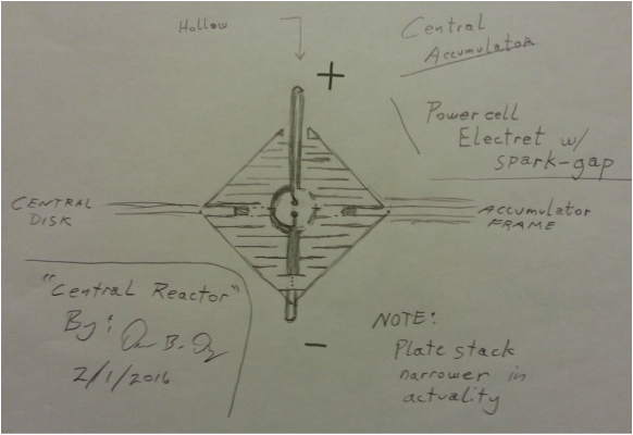
By the way, this design is used with the living electrolyte as a battery with zinc and copper plates. This configuration can be used as a capacitor, but it would require some voltage. Using an electret however, the plates can be stacked just like a capacitor, all in the same polarity positive on the top of each plate, and negative on the bottom of each plate for a DC charge; battery. That later configuration also allows for an external charge to be applied to the central accumulator, and the energy self-organize or otherwise polarize without resisting itself. ... Also an electret power cell would never die, it would be permanent instead of temporary (definition of electret). ... The purpose of the alternating plate stack is for an electrolyte battery, even though such a design is used in capacitors, essentially. But now that negative energy is better understood, a power cell electret would work just fine instead of limiting it to using a living electrolyte only. Interesting to note the similarity between battery and capacitor designs. Electrolyte capacitors and batteries aren't that much different, apparently. (1/1/17)
We can even commutate it or use a Bedini schoolgirl circuit to get the spark in the correct polarity!
If I may make a note on materials of the Central Accumulator. Mixing copper and aluminum will cause corrosion because they react together to create a small current. Eventually the aluminum will be consumed.
I have noticed some flaws in the design above. The bottom electrode has
to run up in an insulated passage to the gap inside, and a wider rim must
be present in the hollow cavity so the spark arcs where one intends it to be
arced (won't arc off the frame).
Hah! Even better. Do away with the top spark gap electrode in the center
of the Central Accumulator, and just run the lower electrode to the direct
center of the inside sphere, like a plasma globe. It would resemble the radius
of the sphere, half the diameter in relation to half the circumference, but as
the PI of a sphere, where the Origin is a point of charge.
---> In parallel, volts don't add, amps do. The Accumulator internal structure is stacked in plates, so it could get up to some voltage (not a whole lot, but maybe 20 to 30 for a small test model). It would be easy to see how many watts an accumulator would generate and the breakdown of volts / amps. Easy enough to design a scale model, and add up the output per each segment. Would be making a bit of a guess, but it could be a close estimate.
I think a Hutchison power cell matrix would just be a whole lot easier overall, also (UPDATE! NO! A LIVING ENERGY BATTERY IS BETTER! ALL THE BELOW MAY NOT HAVE SUCH UPDATE NOTIFICATIONS). We'd be using the whole accumulator instead of halves. It would last forever. Using rubber o-rings to divide each plate stage into segments would make more efficient use of that Power Cell compound since it doesn't produce a whole lot of power. A Central Accumulator of this design can include a hollow space in the middle.
Easy to build.
You can't just do this though: Fill with compound, add a plate. Next segment: Put rubber spacers in, fill with compound, add a plate, repeat. Charge. Hold. Let it cure.
The reason why is because each segment must be charged separately, because each segment won't generate but maybe .8 volts. So the volts would have to stack, so they add up; and in parallel the amps can add up in the wider parts of the Accumulator, using multiple rubber o-ring spacers to create segments that can be connected in parallel and in series, to add up amps and volts.
Each power cell electret shape can be molded into the appropriate shapes and have them pre-charged up. So we just drop it right into the Central Accumulator assembly as we assemble each half.
..............................
Benefits:
last forever (or for a long time, 20 years? Dunno about that part)
It would simplify the wiring of the OTC-X1 (except for the commutator)
Would not require a commutator (actually, it just might after all; see below)
We could easily pulse the current (start and stop it) in the outer electromagnets to obtain field
collapses if we so desire.
Dr. Ning Li of the Huntsville NASA facility was working on a gravity engine using a Bose-Einstein ionic condensate where the charges of the particles were all in alignment, and she rotated a magnetic field over it. She used lasers to stimulate the condensate so the particles spun at a high rate. She ended up seeking funding to further its construction, and ended up leaving NASA and working for the Chinese government. Haven't heard about her since, really.
www.warpmetrics.com ... they also discuss an alignment of charge in a rotating magnetic field.
That's what's happening in the OTC-X1 with the charged utrons, and the rotating magnetic field of the outer "rake" of c-shaped electromagnets.
But whereas Dr. Ning Li was trying to harness the entire mass of the charged particles in condensate, we are already harnessing a significant mass with the spinning gyroscopic action of the utrons. Now this is relative! The weight never changes, but we have an inertial force generated gyroscopically.
EAGLEWORKS-NASA is also wanting to work with a condensate.
PART II
I really want to make sure that this simple concept is known:
When an electromagnetic field collapses, it does so at the "speed of light," at in resonance with the whole coil and all the strands of wires. That field collapse creates a back voltage due to the motion of the field as it collapses rapidly through a field coil. That also creates a very high volt spark if harnessed in a spark gap. That single discharge is what is harnessed to recharge the batteries in a self-regenerating circuit, such as a Bedini schoolgirl circuit.
That same thing happens in an induction coil that generates a spark. That's how it works. (This is for the OTC-X1 Engineer who commented)
Strangely enough, generating an electromagnetic field does not do anything out of the ordinary. A magnetic field collapse also multiplies upon itself in resonance (like how a bar antenna which is a coil of wire must use a magnet in the center to increase its frequency of what radio stations it can receive).
A forceful reversal of a magnetic field collapse, driving another magnetic field in opposite polarity will push a more forceful high volt spark. That is called a "snap reversal."
Such a reversal could be achieved at the "top dead center" point of the utron.
I want to make sure that these dynamics are also understood.
This is also another example of "magnetic field compression" or "condensing" the magnetic field.
Theory:
Let's examine the Central Accumulator shape. Volts stack. Amps are strongest at the width.
What we have is a "lattice." This is also true for the Living Energy Electrolyte Accumulator design.
At the widest edges of the Central Accumulator, the volts stack vertically. The wider plate-stacks will carry the highest volts. That volts stack all the way to the narrow widths of the tips of the Central Accumulator.
What will Amps do?
We can't add each segment up to gain higher amps, because that addition is reserved for voltage only; but that does not mean that the amp-rating for the Central Accumulator is only obtained at the little electrets near the tips, because that discounts all the other amps.
Electricity will also travel along the inside edges of the Central Accumulator housing, which are conical at a 45 degree angle, so half the amps from a horizontal section will add. Where's the other half? How does that affect or transform voltage?
I think the plate stack will also develop some resonance; the difference between a capacitor and a battery is that the battery is self-generating.
This is also why the Central Accumulator has to be much larger in comparison to the outer electromagnets, and the utrons.
A hollow spot can be constructed so when the two Accumulator halves are screwed together, it leaves a hollow sphere in the center, but we don't want to isolate that place in a faraday cage. We want to allow the "guts of the plate stacks" to poke through a bit, maybe using an electrode flush with the inner hollow sphere, but with a little air-gap around the electrode to the inner housing.
That hollow spot will accumulate a charge; but, it may be different than what we're used to, conventionally. A zero pole of a magnet does exist, and you can track it with a piece of magnetic reading paper. There's nothing much going on at the zero, other than inner-folding action of energy upon itself. We could extend a couple of electrodes in that area though, give it some light to see what's going on.
But the electrodes will be charged, and by allowing energy to form in the center, it becomes more dynamic. (see the above diagram). Magneto-Electrostatic Current.
Any time a spark gap is used on a circuit, then that energy primarily becomes magneto-electrostatic; it literally changes the entire nature of the whole system in the most totally remarkable way!
A self-regenerating Bedini circuit will use high volt flyback from the collapse of a magnetic field to recharge the battery. That can be harnessed through a single spark gap as magneto-electrostatic current. However since this battery does not need to be recharged as a power-cell-electret, it would still accumulate a charge from the "spark-space" in the center of the Central Accumulator-Reactor. It has the potential to overcharge.
The spark is easiy to obtain in a Bedini self-regenerative setup, such as what the Living Energy Reactor will do. Just because it has a spark gap to jump, it will still recharge the battery and provide an "over-volt" static charge.
The only theory involving the hollow sphere so far, is involving the "light space" in the middle, for the reason that in a high enough gravity field, that space will not interact very well due to too much of a time dilation involved. The energy of that time dilation can harness a charge, however.
PART III
steering, maneuvering, pilot interface
These are the next to be addressed, which are still being reverse-engineered.
Steering may be accomplished by adjustment of the field coils. 360 degrees in a circle. At 0 degrees, or at 90 degrees, the electromagnets could turn off (or be weakened) in that quarter of an area, and in timing. That would adjust the voltage applied to the utrons, and the ship would drop a little there.
That energy would go toward the rest of the electromagnets, giving 'er a push!
Increasing the voltage to the utrons over an arc at the front of the ship while decreasing the voltage toward the rear arc could pitch the ship up. The ship could roll to the left or right similarly.
Knowing how it works makes it a lot easier to know how to fly it. John Searle's crafts flew in a similar manner.
In an advanced version, rotating electrogravity hull plating can be used using principles of Townsend Brown, to move it laterally in a direction, or adjust the trim. Searle's craft developed a charge on the surface of the skin. A plunger rod would stop that area from developing a charge for an easy way to pilot his style of craft.
The large picture on the home page has a graphic representation of this on the right side about mid-way.
Searle used just a simple form of maneuvering just from a basic hull, merely charged. Positive charge toward the front and negative toward the back will move a ship forward. Adjusting the charge along the wing-tip edges to turn them on or off was Searle's method. Charged hull surface developed naturally due to the rotating magnets of his engine.
A spark discharge however, could be applied to steer the craft, in a collapse or field reversal of an outer electromagnet. As it might suddenly reverse the charge of one utron for an instant, it could affect the motion of the craft.
Thought-piloting the craft would require a photonic interface. Brainwaves emit photons. Photons are magneto-electrostatic waves. There was an easy way to achieve that in the recent past, and so it is an easy thing that will eventually come along. Just as I experienced through my own Tesla electrostatic field, it can also apply in an engine!
Now here is where a living energy battery system might have a serious impact to be compatible with a thought / intention Pilot interface. Chances are it would not work without a living energy component to the Central Accumulator.
It's interesting though that there is a "light space" in the Central Accumulator. I wonder if it will change color per frequency? This would change the entire design of the Central Accumulator, separating the two halves and adjoining them to the central rotating disk frame.
Information (light) of the engine frequencies would have to be known from outside the Central Accumulator. So there must be a design that can incorporate this, so the two halves of the Central Accumulator can be screwed onto the central rotating disk.
A spark gap can be included inside the Central Accumulator.
It can also be a particular bridge. The electrodes of the Central Accumulator can extend also to this region of the internal hollow cavity. It is something to consider. Perhaps Argon gas fills the space, as Tesla was so fond of. A hollow tube going up the drive shaft could be fitted with a crystal globe device, all air tight using pressure bearings if need be. The crystal sphere or globe device might require an electrostatic fractal array inside. See toward the bottom of the Warp Drive News page.
Radiant Rise: That is an electrostatic current that flows out toward air, say from ground. You always put your bare coils, plates, spheres, toroids up away from ground, and openly exposed to air. We've got a ground with the spark gap, and an "open air" with a crystal sphere, even though it may be filled with something like argon gas. Glass will conduct an electrostatic charge also out into the surrounding air of the cockpit.
This applies to the Electret aspect:
If sparks are created right over the utrons, from quickly turning off and on the electromagnets in rotations in a point-style timing around a flywheel type of design, then the collapse of the electromagnet would ultimately spark between the gaps inside the Central Accumulator.
Energy coming from the utrons may not need to be harnessed but only within itself, very likely boosting the output tremendously, of the electro-inertial field shape. Electro-Gravity
Flyback through the electromagnets' own circuit would create a spark, if gapped in the central accumulator. See the mini-section below about "Wiring the Spark Gap."
That perhaps is the easiest way to achieve it. Just merely extend the electrodes of the Central Accumulator close to each other for its own spark gap. We can even use a comutator.
Although with a Hutchison Power Cell Electret usage, it probably wouldn't matter. The only time polarity seems to matter as far as a spark goes is just how a secondary coil is connected after the spark gap down the line. One polarity or the other, it will place more electrostatic energy on either the floor or a ceiling, in a Tesla transformer setup.
The interesting thing about this, though. Let's say there can be a system-wide spark gap at the center of the Central accumulator, in the inner hollow space.
That would be a more direct way of CHARGING the battery! This would be very fun to play with.
It would charge the Accumulator Spherical Center with a static scalar space. That would turn the entire nature of the overall energy into magneto-electrostatic.
Corey Goode, a Secret Space Program whistle blower mentioned two things in a sentence once pertaining to what is required for a basic warp drive: Gravity Cancellation, and a Static Electromagnet.
--- > The Force of Inertia transmitted through a Scalar Field.
WIRING THE SPARK GAP:
This requires a type of Bedini schoolgirl setup. The utrons acts as coils. See the Bedini schoolgirl circuit schematic on the Warp Drive Engineering page.
This would require the utrons to be connected into the circuit. When the electromagnets collapse their field (turned off), that energy has to run back to the Central Accumulator. Historically the OTC-X1 used a self-regenerating circuit. But since it is using a power cell eletret in this design, the battery doesn't need to be re-charged, but we can treat it the same.
It occurs to me, if the electromagnets are turned off, and the circuit is broken, then flyback volts won't return to the Central Accumulator, but must go elsewhere instead. The most logical place is to the utron. A connection by wire to the commutator (see below) would momentarily connect the circuit to the Central "Reactor" for current to flow.
An Example of sparking:
If the power to the electromagnets are shut off like with a commutator function, but using a special type of switch that just barely breaks the contact, then as the electromagnet field collapses, a spark will jump that gap, and travel back to the Central Accumulator spark gap.
We know that the crystal globe in the cockpit changed colors denoting the electrical frequencies of the engine. So that must be included into the engine design however, and so it would involve the utrons, or something that involves a change of frequency (motion, increasing distance -- speed -- between timing points, and the like).
The historic OTC-X1 craft used a self-regenerative circuit, probably the very same circuit used by John Bedini as seen on the warp drive engineering page. Central Accumulator in two separate halves, or otherwise separated by an "accretion disk" with electrodes / contact points. *
One could get creative with the circuit design of a permanent battery, though.
NEW INFO: Check out the Video of how to understand a Bedini circuit on the post just below this one, or just click here and scroll to the end of the article: http://www.warp-drive-physics.com/construction-blog/otc-x1-reverse-engineering-breakthrough
COMMUTATION:
--- > I want to briefly touch on this. There are a number of ways to do this. There is a handy space between the Central Accumulator, and the capacitor plates, and that's the only space we have to work with.
Since wires have to be run to the capacitor plates from the Accumulator (the "Reactor"), then there is a place to lay down some metal contact strips along the circuit route. Very stiff rods can reach, affixed to the electromagnet-support frames close toward the center of the craft, and they can have a rolling ball or metal wheel that rolls along, making contact with the conductive plates, and rolling along, also contacting non-conductive Accumulator framing. It would be better than a brush. Tension can be applied with a spring. It wouldn't wear down any parts.
There is enough space on the original OTC-X1 blueprint to allow contact plates to be positioned far enough apart, on both top and bottom of the Central Rotating Disk Frame affixed to the Central Accumulator "Reactor." They should be far enough apart so no spark will arc across any contact plate. There can be strips further in toward the center, and further out toward the electromagnets, in that "commutating area space" to make sure there is enough space so no sparks will arc needlessly, and cutting power to the electromagnets, shorting across connecting strips.
I've made similar commutators. You just cross the wires over to the opposite ends and reverse the polarity when the current is supposed to be in the opposite polarity of what you'd connect directly to otherwise.
Pretty neat! Utrons also act as coils, so there is plenty of interaction available for a reactive and resonating "spark" magneto-electrostatic circuitry. Since the utrons act not only as inertial generators (solid construction), but also coils, then there very well may be a zero point at top dead center over the utrons, at a magnetic gate or "zero" axis of symmetry.
I would think some sort of additional frame (a wiring platform) would mount to the outer frame and/or inner frame, could even use bearings, to handle all the transmissions of the energy, placed in the space that you can clearly see just right around the Central Accumulator in the image on the next post below. Such a thing could be creatively done.
~.~.~.~.|.~.~.~.~
The images below are an experimental generator / motor I built using two outer coils and then the one large one you see. The outer coils poked inside the big coil, and there is a very large magnet inside. I was experimenting with perpetual energy before I discovered the Bedini School-Girl circuit.
Notice the little round thing at the bottom though. That is the Commutator.
It could either generate AC, or DC, and it could be powered by a car battery (12 volt DC) and generate AC, OR DC. The commutator made all that possible.
This is to satisfy the OTC-X1 Engineer in the comments who wanted more substance behind my words. Thank you, OTC-X1 Engineer for giving me the perfect moment to share this bit about Commutation; from one engineer to another:
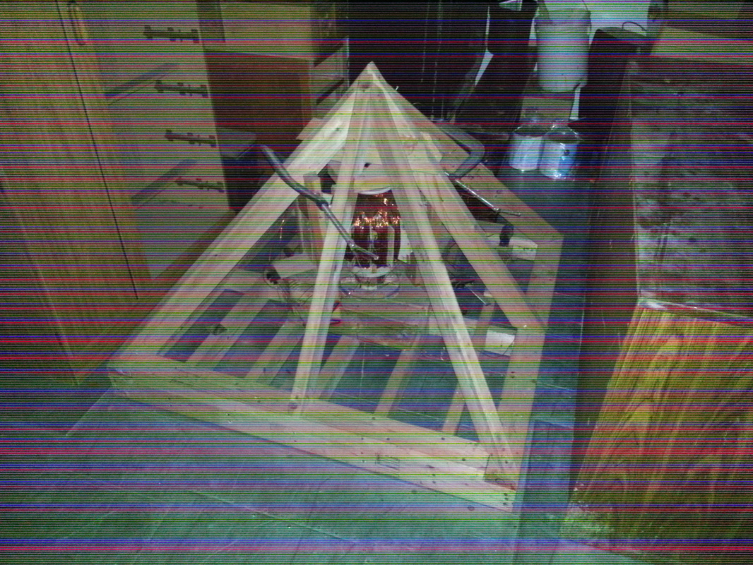

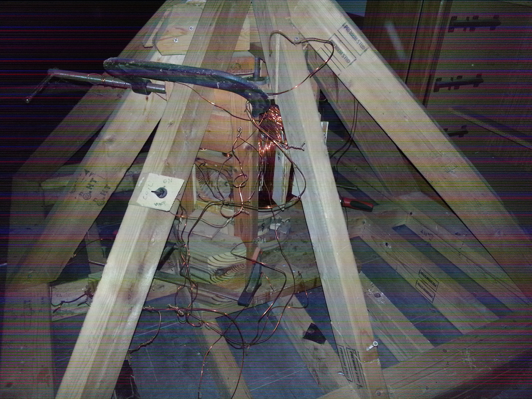
Above: various photos of the generator / motor, itself.
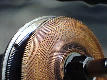
Below: Photos of the Commutator!
Below: Photos of the Commutator!
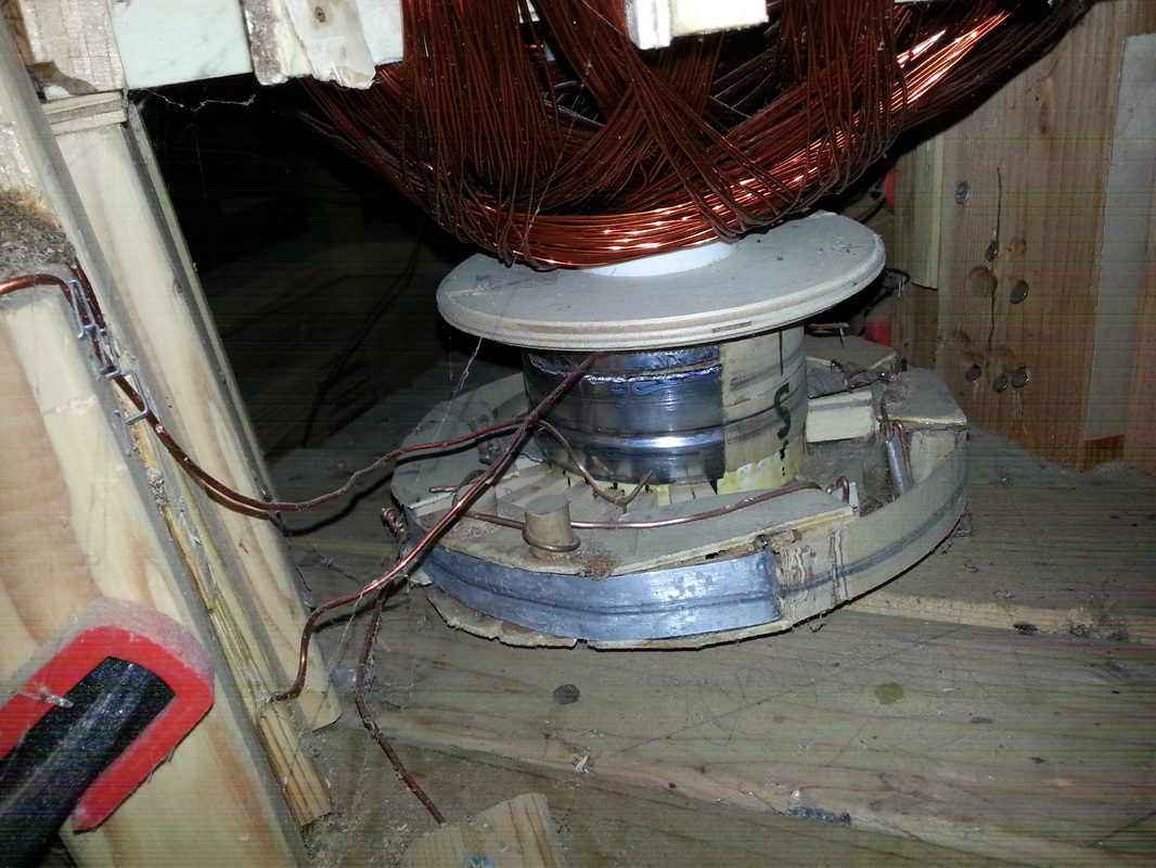
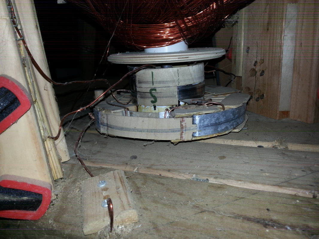
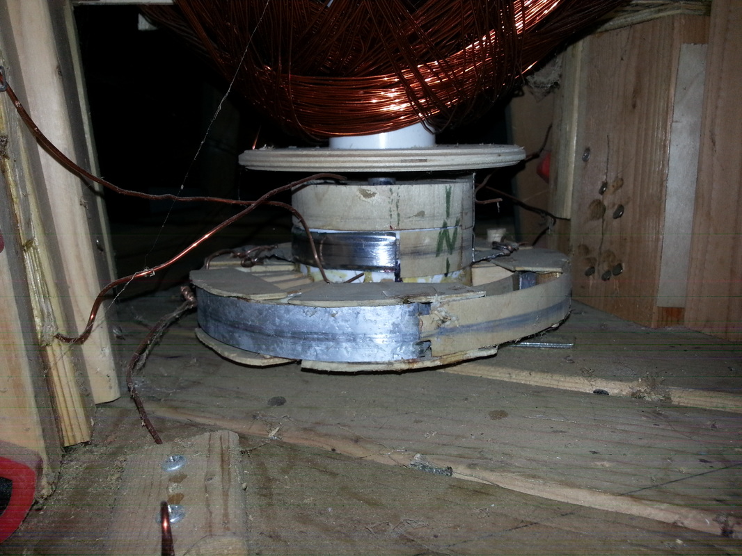
These above are photos of the Commutator. It used 6 wires primarily that could be connected (touching the contact plates). It was a very simple thing to figure out.
The wider disk at the bottom, I could have put that shiny metal conductive plate instead of around the outer edge, but on top of the flat part of the wheel, like how the OTC-X1 commutator can be. There is so much space on the flat central rotating disk (accumulator frame) right beside the Central Accumulator.
The photos above are rough and crude, but the OTC-X1 engine would have to be much more refined than this. The purpose of a commutator is to switch the polarities around so you can get an AC current going in DC. That's it. That's basically its purpose. Naturally, a magnet and a coil of wire generates only in AC. So it's easy to get it to generate an AC current. But, it has to be commutated to generate a DC current.
In a DC generator though (there are several ways to generate pure DC; I've experimented with all of that), sometimes you're going to want AC. You do it exactly the same way, the polarities are reversed at intervals in degrees around a circle. If you want to switch the connections, you have a standard connection (common terminal) of 2 wires, and then you have 4 wires coming in for both polarities of DC current (to alternate). You could just rapidly switch the wires back and forth, criss-crossing and un-crossing, but why do that when we can rotate a wheel, to do it automatically while the wires just stay where they are?
That's the concept. An easy way would be to use your 4 wires, call it "Circuit #1" and "Circuit #2" and have the wires positioned on the wheel in (+,-) and (-,+) polarities. As the wheel turns, you time it by making those wires touch a conductive plate that goes to your common circuit, and then it alternates. It's easy to do. You can either run your common circuit with 4 wires instead of 2. That's probably the most lame way to do it (with 4 wires going to the commutator as the common circuit instead of just 2), but it's not that difficult of a thing to do is my point.
Look VERY closely at it ... you can click on the pictures and zoom in. I screwed up and had to use a dremel to cut the wide plate so I could have an extra "electrical-contact pole" on top. It was one of those "Doh!" moments.
Path of Current:
One thing I learned with this, is that electromagnetic current does indeed take the shortest path (I had to try it). However, electrostatic fields and current are not limited to that. For example, an electromagnetic current can take a winding path along a bare wire around a squirrel cage. If there is bare wire touching metal framing, that current will take the shortest path. You don't have to worry with that limitation using electrostatic current.
Another thing with electromagnetic current used on a bare-wire winding around a squirrel cage, is that an electric field will run in parallel. It does not run around in a spiral, but takes a path from the top of the squirrel cage straight down to the bottom (along z-axis, the height of a cylinder)! Eric Dollard and his genius Ham Radio Operator friends clocked the electrostatic wave (parallel wave) at 220,000 miles per second!
Di-electric current (parallel; electrostatic) can be beamed, just like a radio wave and form a circuit with the ground through a field, and allow for an electromagnetic current to flow through that field without a wire. I tested that with a AA battery (see: Tesla Engineering Physics). I'll put far more detail about that in my book. I found all that out because of my Tesla tower and console. Also, Eric Dollard teaches that.
Magneto-Electrostatic current WILL conduct along an insulated wire (any kind; magnet wire, rubber coated; conduit). An insulated magnet wire wound in a coil in the shape of a long pole -- it will only conduct a static charge only if there's a spark gap. But, it does conduct a static charge in parallel and in tranverse to parallel surfaces! That is what can be considered as "Unified Current."
This also applies to the Vertical Core Vibration Engine, as it creates a scalar magneto-electrostatic inertial field with unidirectional [inertial] force (charge and magnetic inertial - spin alignment).
Rotating Squirrel Cage
That's a possible way to do it. Know what a squirrel cage is? It is the frame, the cage used in electrostatic and magneto-electrostatic coils, like on the Tesla tower photos on the Tesla Engineering Physics page.
Vertical rods mounted to the outer hull that are rigid. They extend down and touch the central disk, and have a bearing on the end touching the central rotating disk (accumulator frame). Circular guide rails on either side of the vertical rods at the central rotating disk (accumulator frame).
Circular metal conductive plates affixed to central rotating disk (accumulator frame as some call it), for purpose of commutation (a Flat Commutator on the accumulator frame in that space between the Central Accumulator and the capacitor plates). The vertical rods are the "wires" that contact the commutator.
That's a cool idea, but the rods would have to be adjusted further in or further out to be on different "commutating tracks," for practical purposes. Otherwise, in a classic squirrel cage, where the rods are all around at the same radius, it might be interesting; Tesla loved his one-wire connections. I imagine one could get pretty creative and fancy with this.
Regardless, a squirrel cage frame would be good and solid to run wiring to contact points.
 RSS Feed