Warp-Drive-Physics.com
See: lightdrive-ascension.com
  • Home
  • Warp Drive News
  • Warp Drive Blog
  • Metaphysics Blog
  • Warp Drive Philosophy
  • Warp Drive Engineering
  • Tesla Engineering Physics
  • Construction
  • Construction Blog
  • Updates and Design Improvements
  • Outer Ring
  • Exo-Archaeoastronomy Blog
  • Planetary News
  • Ascension Blog
  • General Blog
  • Free Energy / Tesla
  • Info

Alexey Chekurkov's Discovery Prompts New Direction, and New Rules

11/10/2018

5 Comments

 
UPDATED 11/19/18
​
Things have swiftly changed around but I wanted to announce that the LAU Trust is now branching out a bit to address the "emergency" of Human transition while keeping security toward existing Earth infrastructure.

Anything going into space is not 100% bound to Earth markets. That's why the electrogravity space engines we use have been declassified. But the technology is only shown to a point ... although anyone can buy a kit online for an EM drive, its not allowed in Earth Markets, for sale, unless it goes into space, or for science discovery. All a non-market policy does is agree to the laws and enforcement already in existence, demonstrating ones understanding of security interests and policies. That's why companies (corporations) have to classify tech, because they operate in clandestine nature to market system (energy infrastructure; Earth-based monetary system) security. Thesedays, the market security extends to guarding against off-world credit-based economic systems (recent disclosures by FED RESERVE and Bank of England regarding money creation). There's treaties with the breakaway civilization. We have been told about it. Notice in private; systems of Law and uniVERSAL commerce laws. So we have duty to guard market systems while addressing the "emergency" that transitions Humanity into higher civilization with antigravity, energy, and warp drive.

There's a whole lot more to it than that, but that's the gist of things. 

This is scientific discovery and research and development, however some aspects cannot be shown in public due to security reasons.  Full disclosure with limitations just makes things a little easier to swallow, considering the magnitude of unfolding Events, currently.  

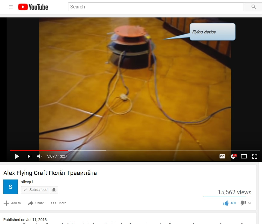
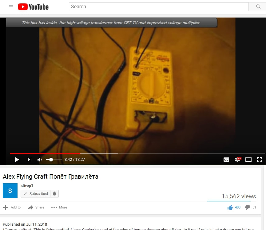
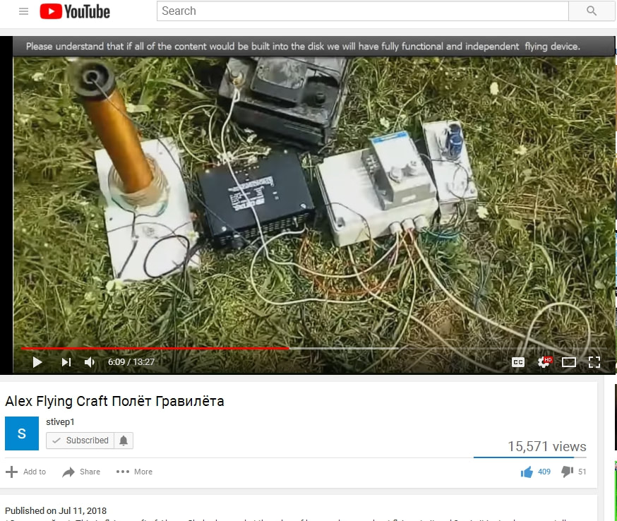
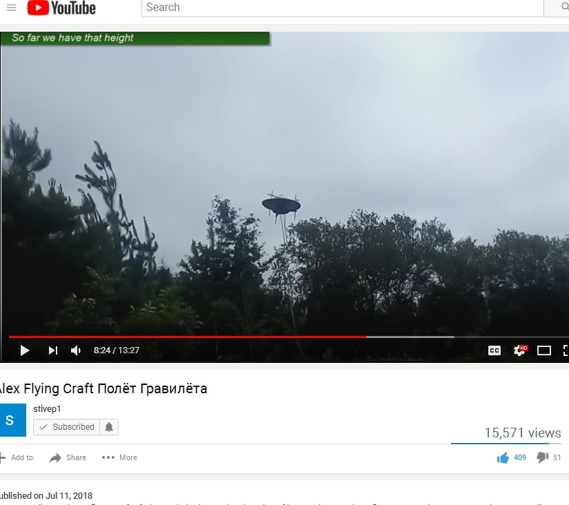
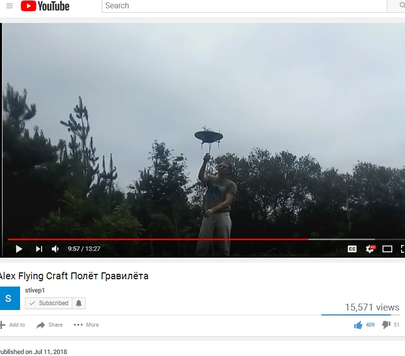
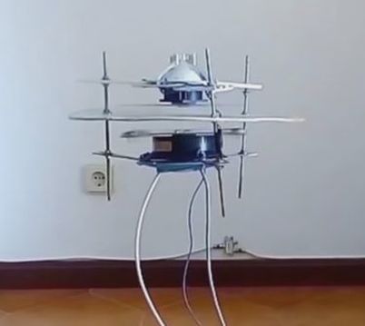
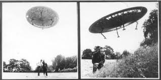
Let me clarify this:  The Alexey Flying Machine is allowed because it demonstrates known physics (as per this website), historic principles of action, and it has an external power source, so its like a limited drone in its current state, and that is allowed.

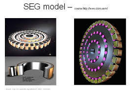
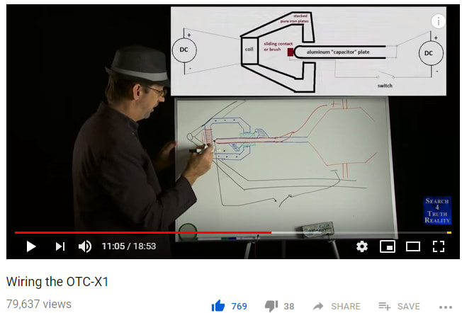
The OTC-X1 is allowed because it uses Bedini architecture (common technology and physics), Bifeld-Brown potential, etc etc..  commonly known engineering physics, and probably in no small part due to this website which has provided the physics to match and explain the device.  It must be classified though as research, and it should be agreed upon that it is not currently even compatible with Earth-based markets because of it's ultimate domain as being able to provide transport beyond Earth.  

This is a huge consideration.  It must be understood that European government had threatened to ban the internal combustion engine and cut out Earth energy markets in favor of new electrical technology and infrastructure which would result in economic war between the elite globalists, and the common man.  If this technology is allowed on the market, in our pre-warp drive civilization, it risks complete destruction and the takeover of any reality of true enlightenment and freedom.

NASA had also openly announced the "threat" to use the "new form of energy" (negative energy/ Tesla technology) as a new electrical infrastructure (multi-trillion dollar industry/proposal).  The reader may think that's a good thing but with job creation ability impeded due to classified markets as things are currently, lack of internship provided through university education, lack of information IN GENERAL enough to educate people toward adapting in a world driven by creation, rather than consumption, and lack of university education in engineering, theory, and physics, and innovation, then people have enough problems right now when children are being born super-intelligent with additional genetic code, only to be incapacitated by modern medicine not designed for use on children whose DNA is more evolved.

(What we take into our bodies, of living energy -- we are living beings why put anything dead into our bodies -- and clean non-tainted foods, along with conscious intent, clarity, focus, eliminating conflict and drama in our lives, raises our frequencies that makes the body immune to dis-ease as our sciences are discovering; but it hasn't caught up with pharmaceutical technologies; and holistic doctors are being systematically killed.  Taking care of our selves requires time, energy, focus, and dedication.  Medicine of natural kind, derived from Earth is not destructive to Earth markets, because it came from Earth and is bound to Earth.   

...   In addition, are children given DNA tests before vaccines to eliminate side effects and death?  Some children are being born with 3 strands of DNA these days, as we ARE evolving; one of the goals of the Human specie is to recombine the atrophied DNA separated from the main strands purposefully long ago in the ancient times where we were way more advanced than we are currently.  Canada has developed cure for cancer for $20 bucks but it's so inexpensive that Big Pharma doesn't want to touch it.  Maybe that says a lot for cheaper forms of space propulsion as well.  Food for thought.)

We are changing as a specie, and the disruption of our economic system when many are only now starting to fully understand it, and the reason for classification of technology, including the dynamics of energy and exchange between Earth and off-world breakaway civilizations, before we even have laws set in place to eliminate debt and switch the world over to credit-driven system, would destroy our civilization.  

Technology is declassified based on Humanity's ability to demonstrate responsibility.  

So, even though the OTC-X1 can be shown working at this point, it should be expected to take some time to show it, and there should only be one purpose at this point for it -- the development of warp drive public spaceports, which are supported by Earth energy infrastructure (see:   
https://www.warp-drive-physics.com/info/funding-goals-and-nondisruptive-logistics).  There is Earth security in place currently to prevent this technology from taking over Earth markets.  

Private markets, private contract, technology trade is allowed as I understand it, so as long as it is private trade between individuals or small groups that do not affect the overall wellness of Earth energy markets..   I have vested interest in both so this is a particular challenge for me.  If you can build it on your own, charge your own batteries, power your house, then don't tell anyone, are the general rules at this point, but now you can apply it toward a common objective such as warp drive spaceports.  

You CAN publish schematics on your own for a donation, as some have done, for fair and honorable exchanges between individuals.  But when you apply for that patent, it is assumed you desire to enter the markets (you have declared your intent to enter the world markets), and that's when stuff gets classified and shelved for 30 years and you may or may not get paid.  Angel investors is a way to get paid for your work, but it results in the immediate classification of it, and you can't ever talk about it or work on it again.  There is security in place for purposes of Earth Defense.

We can call this the "Men in Black" policy


Keep in mind, Article 1 of the U.S. Constitution guarantees that government cannot interfere with private contract.  It is not the goals of the LAU Trust to TEACH Private contract, either.  Lots of problems can be solved by people with integrity and responsibility, as well as knowledge, through an avenue of private contract, so long as it is understood why things are the way that they are.  That is difficult because so much about law, science, trade, history, etc has been hidden and only recently coming out now that it can be protected.  Not everyone needs to know everything, I agree.  But there is a MASSIVE need to know about a lot of things, to prevent a condition of extreme emergency due to Human evolution and the Human integration with the rest of the life in the universe.  It's a completely natural process, but can seem un-natural and a threat, if education isn't provided, and if there is loss forced on others.

What about that $20 cure for cancer from Canada?  There's a lot of problems that cannot be solved due to the classified reality like ET living among us and married to Earth humans but not having kids due to Big Pharma gone wild.  The Human genome is healing but now Big Pharma has a whole bunch of vaccines and drugs pumping into young Human children; do they know the truth, or are they in the dark?  We just don't know everything, and it is unclear how many mainstream scientists involved in projects such as warp drive and bio-tech are purposefully concealing things that are good for us, due to the general inclination of the Human race to (A) want someone to solve our problems for us, (B) not be able to work together for highest-good goals due to greed and money, and ignorance of law and science, etc in general, and (C) well take your pick of reasons: fear and control.

Human evolution is happening.  People are coming forward with amazing abilities like being able to start fires using their mind and their chi.  People are becoming VERY psychic with abilities like telekinesis and telepathy (most people are becoming telepathic as the frequencies of Earth and the star system is raising due to the influx of cosmic energy from the galactic core -- Source Field Energy).  Telemechanics too is an ability to be able to intuitively understand technology and build things due to the knowing being on a genetic level and soul level.  Also the ability to understand timelines, working with the energies of time is a readily and easy-to-develop gift Humans are developing.  

Change is forced upon us from within our own genetics, within our own soul purposes.  It may seem like foreign influence but it's from within Humanity itself, and that can seem very scary until one is able to understand and balance the new energies that Humanity is Inner-Generating.  These changes occur on the Soul level, which manifests and arranges DNA accordingly.  No box can be built to contain the phenomenal life-genesis energy which filters down from higher density and higher dimensions, that pours forth from within Creation itself.  It's like trying to build a shell around Earth to block out light, not understanding that light is all matter regardless; that matter is a paradoxical form of light, and that the material world is but a shadow of the greater reality that creates the physical material in the first place.  With enough education, when one directs one's Soul-Force, one can change (heal and form new bridges upon) one's own DNA.

The only reason this knowledge is not generally accepted or considered, even though medical textbooks and scientists are explaining these things, is because there is no market value in it (so we can create and co-create reality, but where's the money in that?).  The market is not Earth reality, the market is a tool and a mechanism.  It's people that really need to change in this situation, not the markets.  Maybe eventually there can be some balance between those who value life, and those who only value money.  There are so many unknowns in the world currently that one MUST follow one's intuition and FEELING to discern the truth.  Our Feeling center (those chakras that detect emotion, and other people's intentions, and merge through time to bring us information about probable timelines) is directly connected to the Innate and Grand Knowing of the Soul (The source of one's own being; beyond time; whole being; no paradox).  By feeling alone, martial arts for example is 10-20 times faster than what the normal cognitive mind can process, and this is a good point because our "reptilian" brain stem is capable of processing information 10 - 20 times faster than cognition; the brain stem deals with feeling.  That should help to put it in a frame of reference.  


Also ...  last point here:  People have to learn things on their own, through their own desires.  Want, or desire, is a fundamental Force of Creation.  That is also part of the safeguarded "security system" of this planetary reality.  ....  Nothing ever handed out on a silver platter can be expected to be received, because people have to earn it for it to be considered to hold value.  Those are ancient traditions.  The foundation of Earth civilization this recent go around (Sumeria) have been set up with limitations and rules regarding philosophies far beyond what most people ever think about, prior to Human evolution.  There is no Creative Force behind something or some way of living that is undesired. 


​
​. . .


Otherwise, at this point it is unlikely that current engineering physics theory will change much, but only become more refined as time goes on.


​


Addendum:

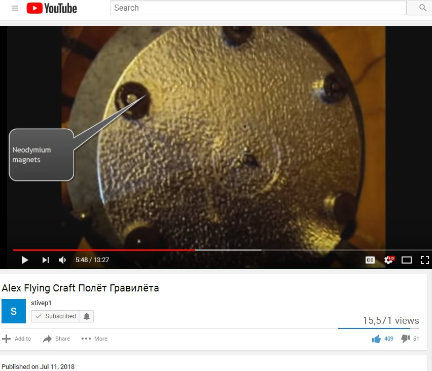
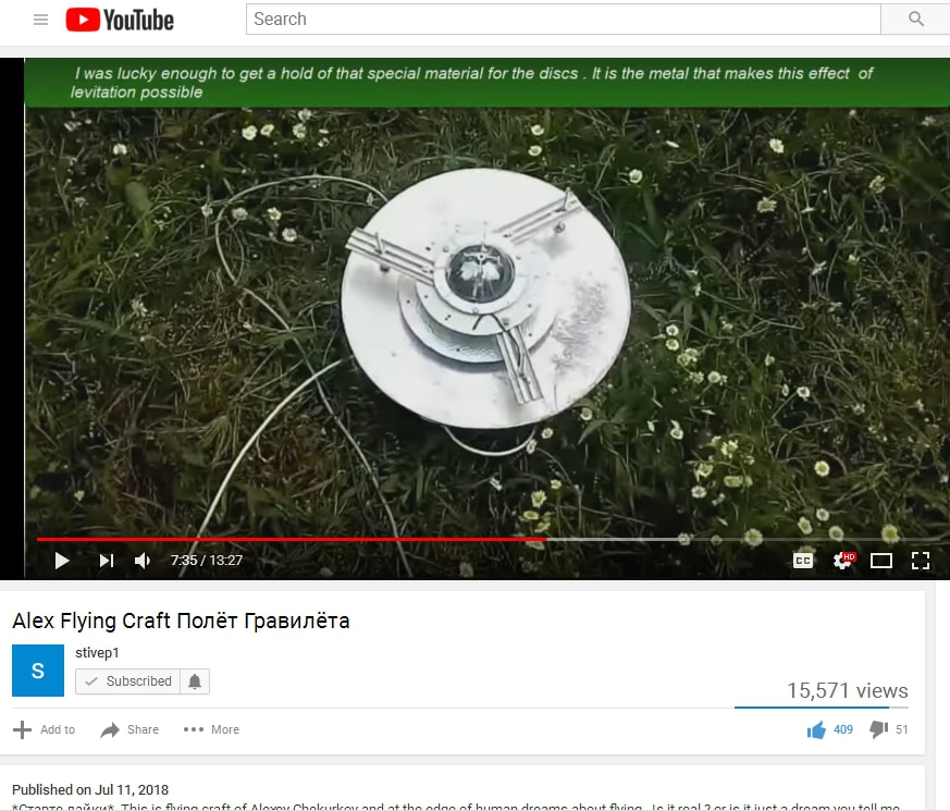
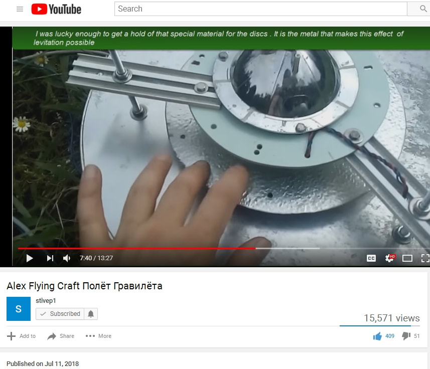
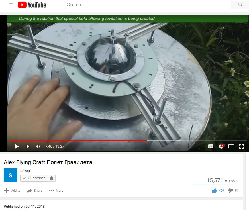
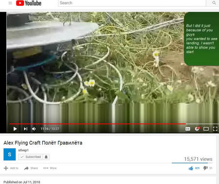
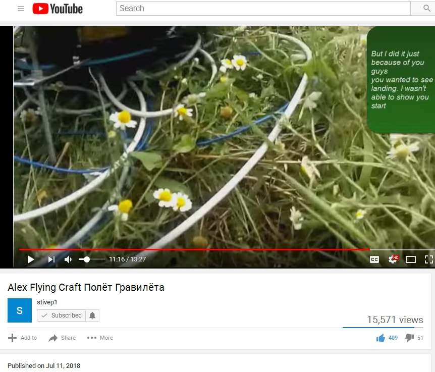
It has come to my attention that now that the Alexey Chekurkov Flying Device is demonstrated, people have turned away from the OTC-X1, thinking it's bogus.  I'm LIVID at this and PISSED that after all this time, the Alexey device has proved the co-counter disk high voltage rotation EM effect, but now people are looking the other direction, not seeing the value of a SELF-POWERED ANTIGRAVITY ENGINE.  I'm THIS close to calling it quits.  

No.  I got a better idea.  This website might go silent for a while while I'm working on that idea.  

There's gonna be some protocols for people contacting this website from now on.  


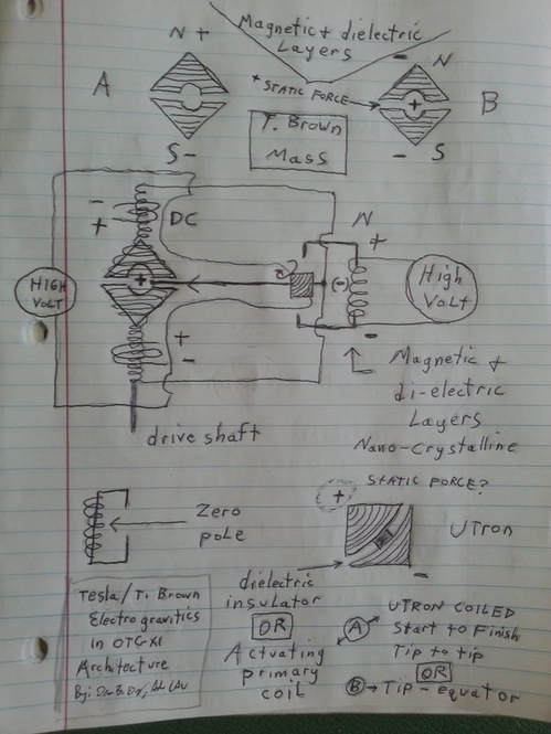
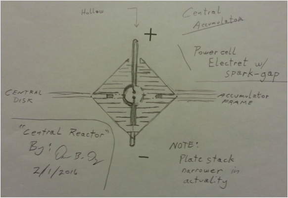
But first of all let me once again briefly explain the  OTC-X1, and the criteria for that component leading to a warp drive reality, which is different yet very similar to the Alexey Flying Device, involving "di-electric gravity":


​
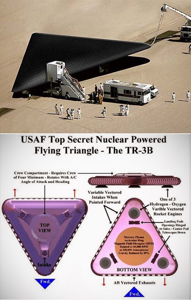
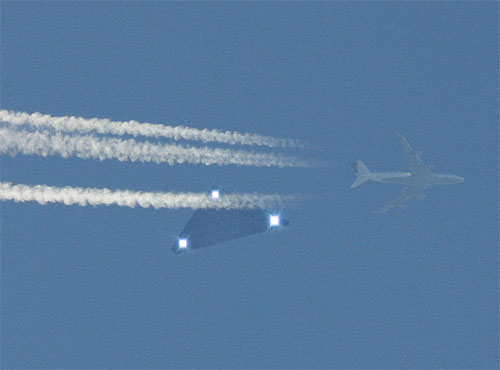
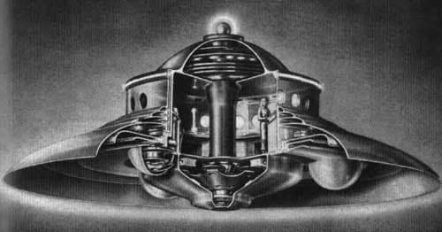
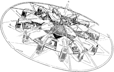
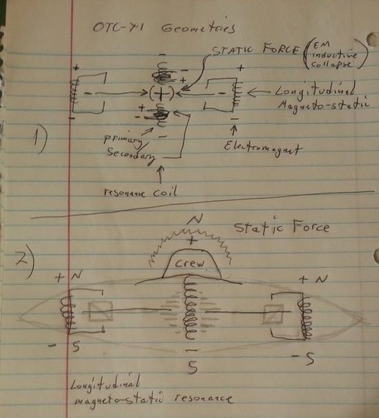
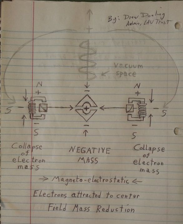
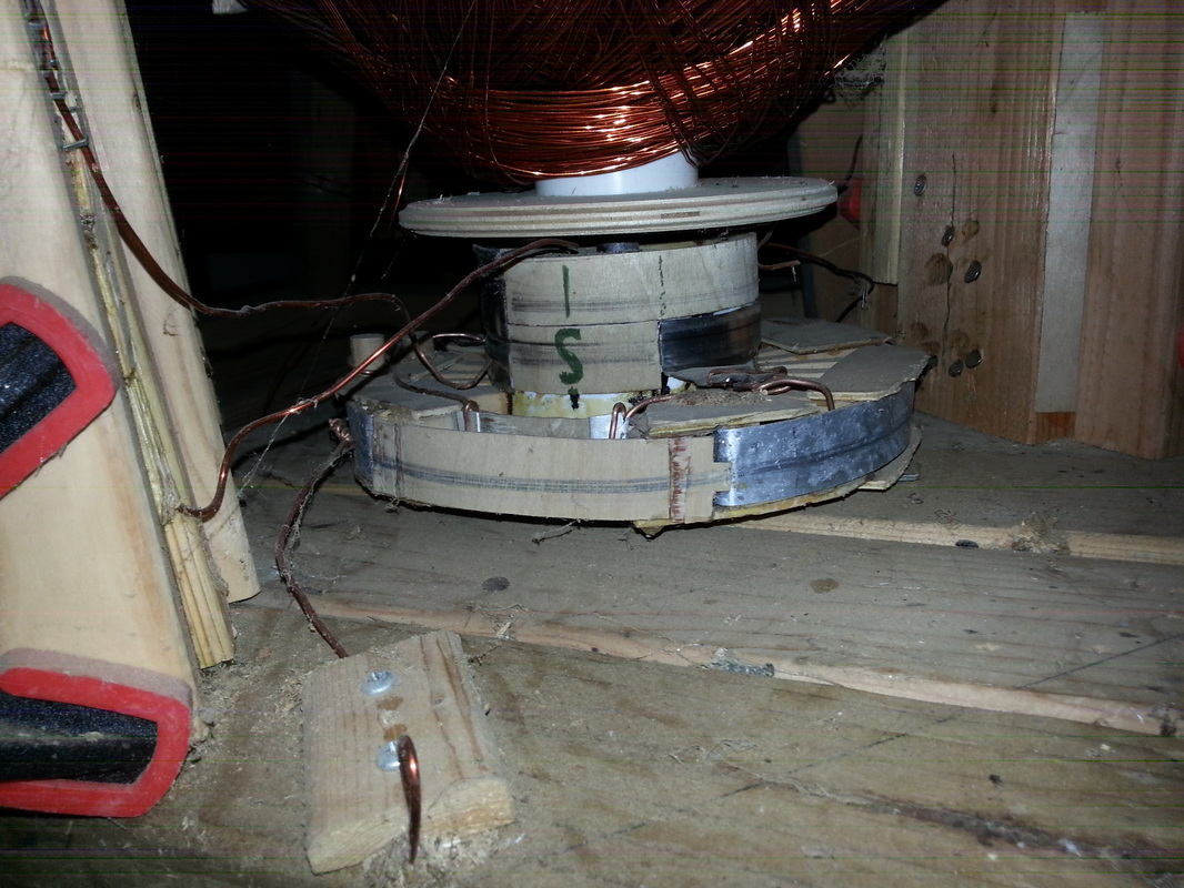
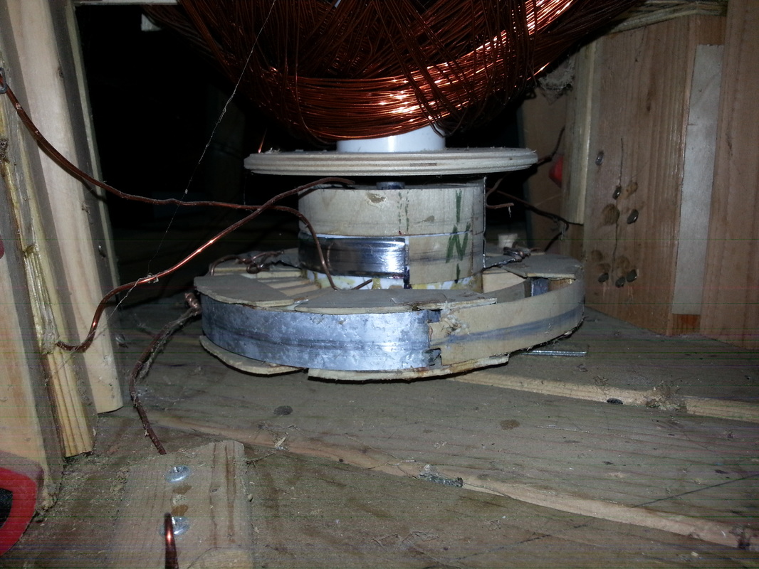
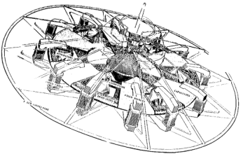
1)   self-powered antigravity.  The OTC-X1 is theoretically a gravity drive, specifically a mass-reduction negative energy field generator, inertial / gravity cancellation engine.  This is why the director of Lockheed-Martin's Skunkworks division said that ESP pilots these types of craft, because the craft becomes so Light that thought and intent alone steers and directs the craft's movement.
​

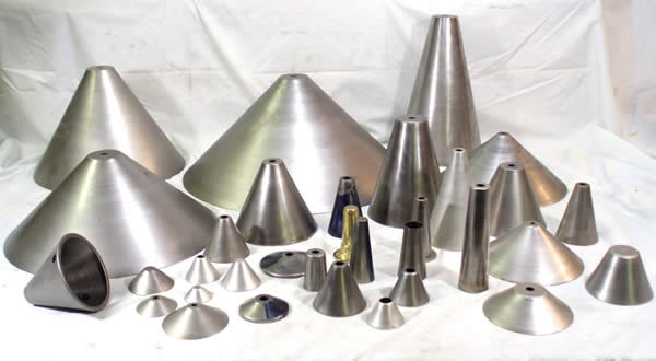
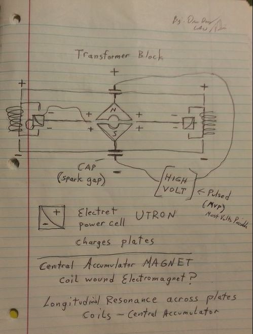
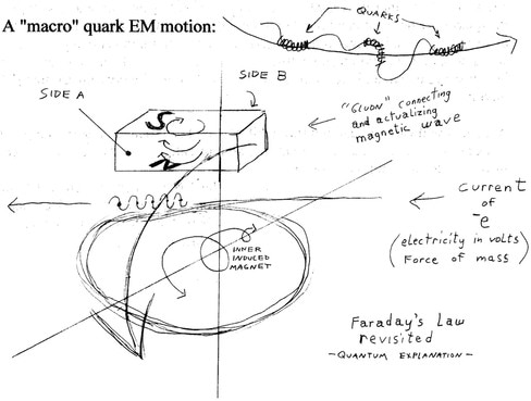
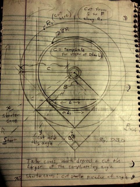
2)   utrons as high voltage capacitors as part of the power architecture and high voltage framework -- to charge the disk plates; their shape aligns the negative energy (longitudinal di-pole)  field characteristics.  Electric and magnetic wave directions are in transverse (90) and the utron shape takes the 45 degree path in the intersection of the E and the M, in alignment with di-ELECTRIC poles.  This may change the wave-shape so that it is no longer in electromagnetic characteristics (non-EM electrical wave is usually a scalar or longitudinal wave; negative energy).


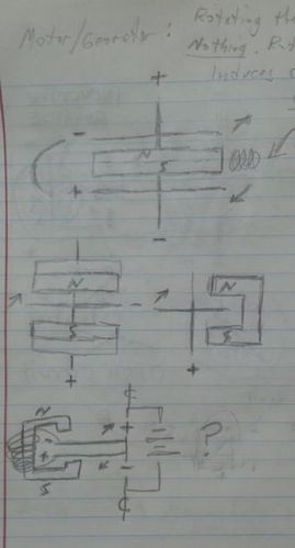
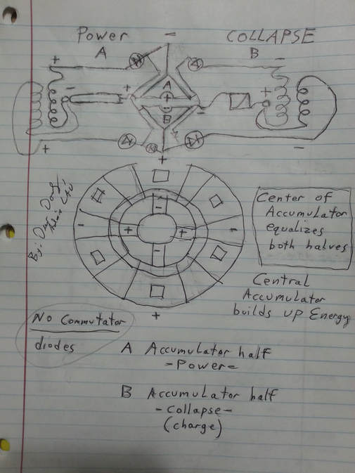
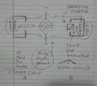
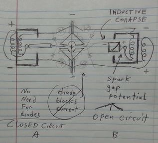
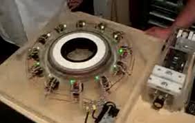
3)   outer electromagnets to power the disk (set it in motion spinning) and provide high-voltage flyback upon field collapse for electro-inertia (charges utrons that charge the plates; charges plates; can be in regenerative cycle with central accumulator)...  (collapse of electron mass through di-electric medium of the accretion disk to the central accumulator of negative mass). 


4)   central accumulator power supply in Biefeld-Brown characteristics of the dielectric/electret active mass component (or central accumulator design with living electrolyte energy)
​

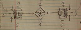
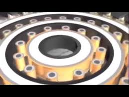
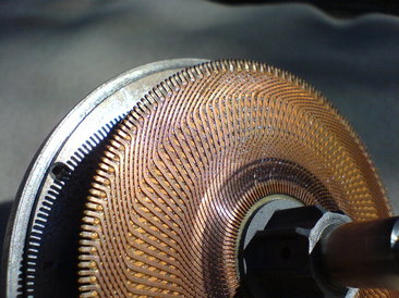
​5)    rotating charge disk also with Biefeld-Brown characteristics (electret-dielectric material "sandwich"), however the Alexey Device has also shown us a thing or two how electromagnetic and electrostatic fields interact according to the physics, and there are some good engineers out there and patent holders in antigravity that say only one spinning disk may be required due to the co-counter rotation of the electromagnets with the high voltage disk.


6)   Bedini-Williams regenerative overunity power architecture and negative energy framework


Additional protocols may be added in the future (one active protocol is that if you are not currently working on engineering a device, namely the OTC-X1 or related technology, you don't have a voice to be heard, as that policy was preferred on the now defunct Clandestine Disclosure group). 

​If after 5 - 10 years some working OTC-X1 technology rears its ugly head here at this website, there will be a demonstration, but large portions of it classified to the public.  For reasons.  Otherwise, I'd be more than happy to shove a demonstration up the ..  nose ... of the construction blog . . . . .    for ..  moral reasons.

​

​


​


​
5 Comments

Antigravity Demonstration Using Counter-Rotating Magnet-Electrostatic Fields From Russia

8/6/2018

73 Comments

 
NOW UPDATED:  Explanation on How It Works, below in PART V


​
Rotating and counter-rotating charges antigravity demonostrated in Russia with an un-identified (update: now it's identified) metallic alloy.


Please check out the research of Alexey Chekurkov, who created the Alex Flying Craft. 


Special thanks to Walter Nowosad for sharing this.   


"Special Metal" is unknown.  It looks like hammered tin, or an aluminum/bismuth alloy, hand-forged.  It looks coated; plated, and easy to machine.  It is known that the disks may become magnetized, meaning it is a ferrous alloy.  It won't work when the disks are magnetized, probably causing a problem with spinning, or otherwise electrical disruption due to homopolar motor effects back-feeding into the external high voltage power supply.

He does have a lot of that metal on hand, however.  He has made other apparatus from that metal, as per links below.  It resembles an iron / tin allow for corrugated roofs with perhaps, a galvanized zinc plating.

It would most probably be a standard type of easily-acquirable metal.


Also note the power supply in the video below, using a Tesla resonance transformer.  His standard power supplies however are using "positive energy," rather; whereas these metal disks are essentially rotating air capacitors.  Being able to conduct magneto-electrostatic fields and usage of the Tesla resonance transformer denote that they are charged as a field at high volts, using non-standard electromagnetic (positive) energy; and the electromagnetic energy from the transformers would be going toward powering the motors that spin the disks, not using homopolar motor technology.

​Note the blending of the energies of magneto-electrostatic and electromagnetic in high volts.


Furthermore, he uses neodymium magnets in the positions of the utrons near the outsides of his lower disk.  The magnetic field near the outside while spinning them, denotes the electromagnetic collapse of magnetism toward the center -- in that field geometry.  

This begs the question of the utrons being magnetic, whereas the outer electromagnets of the X1 collapse somehow in timing with the passing utrons, and a coil around the utrons could be built to handle that collapsed energy in polarity opposite of the utron-magnet, to deaden or cancel the utron's magnetic field in order to pass through the electromagnetic gate.  

Aside from that complex structure, a homopolar motor design with electrostatic rotating disks may actually be able to handle rotating magnets spinning in the opposite direction of one of two counter-rotating field disks; it seems that the rotating magnetic fields are only traveling in one direction.


It's easy to see the device comprised of two capacitor sets, one on top (with lower rotating disk), and one on the bottom, with lower rotating disk with magnets.  He is NOT using homopolar motor technology, and he's using an external Tesla coil power supply, instead of integrating that into his design, although it is using a conductive hollow "hat" similar to a Tesla tower.   Also note the static disk, rather the disk that is not moving, with the frame "landing legs" sticking through it.

Note the bottom rotating disk is wider than the upper rotating disk, keeping to principles of the magnet and dielectric layers, using a wider magnet on bottom and on upper magnet, in less width, in adherence with the Townsend Brown in a vacuum test shown on the pdf file on the Construction page in the Townsend Brown section.


Part of it is powered through a Tesla resonance coil.


Here are some of Alexey's comments:

"A new lightening disk was made and a video was shot. But someone influential complained and yutub blocked the roller. But one user managed to download and reapply but again called feykovy flight. He decided that if the terminal with akamulyatora removed means fake. But I explained that from time to time you need to remove the power from the TDX to prevent the magnetization of the disks and prevent the subsidence of the parameters. If you have not seen the movie, I'll throw the link."


Here, we see the same metal on this video, which is not a YouTube video:

https://thexvid.com/video/_LZ0-dQxKwI/%D0%B1%D0%BB%D0%BE%D0%BA-%D0%BF%D0%B0%D0%BD%D0%B5%D0%BB%D0%B8-%D0%B3%D1%80%D0%B5%D0%B1%D0%B5%D0%BD%D0%BD%D0%B8%D0%BA%D0%BE%D0%B2%D0%B0-%D1%82%D0%B5%D1%81%D1%82%D0%B8%D1%80%D0%BE%D0%B2%D0%B0%D0%BD%D0%B8%D0%B5.html


Okay, here's the YouTube video of the above link:
​
Notice how those can resemble OTC-X1 central rotating disk segments ???  Check out the cheat sheet on the article below . . .
​
Following his research, you can see more about the field flows here:
​


AND ...  BAM!  Found the type of metal he's using:

"This corrugated aluminum with an anodized coating structure similar to the beetle fenders. So successfully coincided."   


Guess I need to mention Alexey mentioned in a comment on one of his bug wing videos what the material is -- the anodized corrugated aluminum. I spent hours translating Russian into English and searching.
​


This represents the first successful testing of the rotating and counter-rotating charge antigravity craft, able to lift a considerable amount of weight, and when applied in an air-tight resonance cavity hull may also work in a vacuum.

So now we know that the rotating and counter-rotating charge principle of physics DOES WORK.


​


PART II

I want to take some still-shots of the videos, and notes, to have a photo reference, just in case, because Alexey mentioned that his prior videos were removed from YouTube in order to suppress the technology.  

He uses modified high voltage power supply from switching power supply for his original test.  The first disk is powered up using a standard motor, plugged into a wall socket (power strip) which gets it to spin, as is the second disk.  The disks are mounted to stationary frame (stationary disk), which the two motors are bolted to.  The disks are arranged as capacitors, so the presence of unmoving disks in the engine will not cause it not to work.

After the two disks (the one on the very bottom, and the second one from the top) are spinning in opposite directions, most definitely.  You can adjust your video settings for high quality to see better.  The next step is to connect the high voltage power supply (after all, as I've said before, all forms of electrogravity use high voltage).  In the OTC-X1, that is achieved through high volt flyback from the electromagnets.

Okay.  The high voltage is plugged into the stationary disks by the looks of things, and the rotating disks picks up one polarity of the dielectric charges, but both stationary disks are on top of the rotating disks, so the orientation typically used is positive up and negative on bottom.  If using positive on the bottom, it would be repulsive to the Earth surface charge, and not achieve significant height, in my opinion.

The orientation of negative on bottom and positive on top effectively means that the co-counter-rotating disks are spinning positive against negative, looking at this in the form of capacitor geometry.  His high voltage source is the typical high voltage transformer from a CRT tube and improvised voltage multiplier (positive energy high volts, just like most people do with their electrostatic lifters).  You can hear the zzzzzaping when he plugs in the voltage multiplier.  

​
​High voltage supply is the box in the middle photo.  Multiplier is the hand-held device on the floor in the right photo.


He says the high voltage performs the "magnetization of sectors."  It's in Russian, but there is an English translation.  

Voltage and speed  (inertial frequency).

The bottom left is levitating.  Bottom middle is side profile.  Bottom right is the bottom of the engine, and those are the 6 neodymium magnets.
​


PART III


Okay so here is the successful test model version 2.

The mess on the left is the power supply.  Tesla resonance transformer, and immediately to its right is the power supply for it.  The box on the far right is the independent power supply for the transformer block, and the little white box on top of the big white box is the high volt power supply.  It's all connected to the 12 volt battery.  I'm recording this for posterity, just in case.

Alexey continues to explain that a conflict of sequences steps caused his previous model to fall down, and he has to do a lot of fancy adjustments to get the craft to go up in the air, and sometimes it may take 30 minutes to balance everything correctly.  Basically he explains that his power supply system has to be charged up in a certain order, probably due to resonance, like how a capacitor has to be charged first in a basic LC circuit (see the article below), and then when resonance starts to break down, he needs to provide an input to the capacitors, but it ends up going to the wrong place (the transformer instead of the capacitors), and his high voltage signal starts to degrade.

I don't want to speculate here too much about his power system, though.  Not yet.


​The second device, his working prototype is impressive, and obviously upgraded from the first, yet still having the same overall characteristics, and using better field geometry.  

We know now that he is using corrugated aluminum with an anodized coating, which was the same material he used for the CSE beetle (sound resonance cavity) experiments, from the Russian etymologist years ago who discovered that effect.  The piece he is touching is the upper rotating disk.  This is awesome!  It's like a TR-3B engine (1 of 3 on the triangular hull's tips).  Just think how this style can be adopted to use a homopolar motor design instead of dipole standard electric motors.

Here below is a better view of the whole top.  The special field is theorized in different ways.  One theory is a positive and negative electrical mass cancellation.  Otherwise it's not very well known how it works to be honest.  If you consider electromagnetic spin reverses on either side, up and down, left and right within orientation to electric fields relative to a plane of gravity, then the spin one way and spin the other way seems to cancel gravity, along the middle and much wider disk plane.  

Magnets are involved, however.  In fact, the article below this one showing the little diagram of the outer electromagnets in homopolar motor configuration spinning two disks in opposite directions is similar but I REALLY LOVE the concept of the centralized wider disk in Alexey's application.  Similar to magneto-electrostatic, or just static electricity with the two counter-rotating disks creating electrostatic friction on the central wide disk.  The two rotating disks appear similar in size.  

​If you notice also where the high volt top disk is, it is connected via frame to the central disk, but later on it shows Alexey touching the legs of the device during levitation, and touching the bottom middle.

He uses three wires:  one high volt from the Tesla resonance transformer, and two wires from the rotating disks.  I would say he is using a homopolar motor design in this version, due to only two wires to handle the rotating disks, and the third as the high volt magneto-electrostatic feed.  
. . .
Picture
Here is the best profile shot I could capture.  You can see the wide disk, landing struts (frame), a tiny sliver of the top rotor disk, and the bottom rotor disk.

Note also in the bottom photos, a contact strip from the legs reaching out to touch the rotating bottom disk area, probably to transfer the charge, as a brush.  

It does not look like there are magnets on the bottom of the disk, though.


​It looks like the magnet is above the lower disk, and if you think about a homopolar motor, then it would seem to act in just that way.


So there you have it!

Different styles and designs.  Makes me wonder about the OTC-X1 now -- counter-rotating electromagnetic field versus counter-rotating electrostatic disk.  

Make sure you click on the images to magnify them and see the whole image.
​
​


PART IV


So we have a successful flight test, on two occasions (original model and remake), which looks fairly legitimate; and although Alexey didn't get his camera up close to his craft as it was levitating so we could get a really good super close inspection of it (he may be wanting to keep some proprietary secrets, who knows), at the very least it is demonstrating a familiar geometry:

A rotating electrostatic disk, in counter rotation to a rotating magnetic and electric disk.  The lower disk is separating the magnetic and the electric aspects (rotating magnetic field, coinciding with a rotating electrostatic field) in BOTH designs of his.  The upper disk remains a constant variable, but the shape of the engine itself has changed (which is okay).

His power system is many times larger than his test craft.  The OTC-X1 however includes a potentially self-contained power system in its design, which is why we favor the OTC-X1 for the ultimate craft, yet engines like Alexey's are favored in the testing phase to understand the physics and the power systems.

Yet, we still need to understand how the OTC-X1 works, and Alexey's design is a practical application toward achieving this goal.  


From the articles below, we can see how all these systems co-relate, and there is a pattern:

Counter-rotation of electromagnetic and electrostatic rings / disks.  There must be a magnet involved, and there must be electrostatic involved, and high voltage, but we can simplify the energy requirements using flyback from the collapse of the electromagnetic coils, while also using those electromagnetic coils as our rotating magnets.  After all, a homopolar motor will work in many combinations, in both two-piece and one-piece dynamics.

The utrons also double as rotating magnets, and static field generators.  The utrons are in the same place as Alexey's original experimental device, 6 of them around the perimeter, but are oriented along the 45 degree inclination / intercept; and we have some comfortable spacing in between the OTC-X1 components for timing the engine pulses and collapses.  

The OTC-X1 blends Searl and Alexey 
Chekurkov designs.  


I would like to open up the Comments field at this point, to gain some much-needed feedback from others about any ideas and discoveries and tests that can be brought to the table of our common goals.

​


I want to hit some basic highlights however, just to make it easier for the newbies to do a search on.


Highlights:

​
1)   There has to be a magnet to get the device to spin, but the unifying principle seems to be co-counter-rotating electrostatic high voltage disks.  (although rotating electromagnetic fields can be intrinsic)

Sources of high voltage:

Capacitance and flyback (utron kinda remind me of doornob capacitors). Utrons act as high volt capacitors.  

Don't discount the central accumulator from being able to store high volt capacitance from the flyback. It's strange gotta admit. Capacitance would help raise frequency otherwise there would be a pulsed mechanical frequency that needs to be raised thru resonance and capacitance.


2)    I mentioned i'm going to use an induction coil for some tests.. and I got to thinking one big coil could equal a bunch of smaller coils but would still need capacitance to equal what one big coil can do. 


3)    It would not be a stretch at this point to consider the OTC-X1 as a flying induction coil. If you eliminate the complex scalar warp drive physics and just stick to engineering, one could make better sense of all this mess from doing some creative experiments. 

The one noteworthy thing about the utron / accumulator 45 degree cone shapes tho is the intersection of parallel / longitudinal electric and transverse magnetic fields. THAT is probably the ONLY reason they are significant.

​
​

4)    THAT is what scalar energy is about. Actually no that's what NEGATIVE energy is about. Without that component there's no guarantee it will warp time ... and furthermore cones within cones may make a better crystal power cell electret material alignment in the central accumulator than flat plates in the accumulator.

That means there will be a mini utron-shaped hollow cavity inside the central accumulator. 

That also might be the reason the X1 is able to hold its own self-regenerating overunity power system. 

Each interior cone segment can have individual electret "sticks" arranged in cone shape too, basically sub-dividing each cone section so the electret material can be better electrified/magnetized.


​5)    This from Matt Tracy ... in regard to Bismuth and Aluminum alloy in Roswell crash - Arts parts:

"Now I do know that both bismuth and aluminum are paramagnetic. And i also know that bismuth has two very interesting qualities to say the least. Bismuth when flattened to 5-microns or less becomes naturally superconductive at room temperature. Bismuth's second amazing quality is that it is naturally at the atomic scale has an asymmetrical atomic geometry. And we know that it requires asymmetry in the dielectric field to produce a counter wave to asymmetrical dielectric fractal emission that we we ignorantly call gravity."

Aluminum anodized with bismuth is a good idea. I also know of bismuth becoming superconductive in small slivers. Graphite too has similar properties in thin wafers. Diamagnetic or something if memory serves. Able to reflect the magnetic field perfectly to hover a magnet over it.

UPDATE:  there is no need for bismuth since a rotating aluminum disk acts diamagnetically upon a magnet, reflecting the magnet's poles.


6)    Also ... just because a system may be generating negative energy, it does NOT mean a system is reducing mass, and suddenly a large craft has nill inertia. These are specific fields and the only way to explain them is to show their relationship with action. 

If something has no inertia, that is a local field effect and due to a field effect. By now, everyone knows how UFO and TR-3B craft move in their sudden accelerations and right angled turns that don't squish the pilots.

But an electromagnetic field collapse does not make the coil weigh less; but if that force can be harnessed in scalar ways in high frequency, in a perpetual energy of collapse without it filling up, and thus increasing energy output, THEN it's something.

And even tho Stephen Hawking says the total energy of the universe is zero due to negative and positive energy, it does not mean that negative energy is the absence of energy. That is a dumbass assumption. 

And I really apologize to those still stuck thinking that opposing fields cancel mass when opposing fields only cancel energy output to zero and they're not even able to get a basic generator to work because they wind their coils in opposition. I don't know what to tell those people who absolutely lack and practical experience and have never wound a coil in their life.

I'm just very careful not to call flyback voltage negative energy, because if it's not overunity, it's not necessarily negative energy.  It may have its BASIS in the collapse of an electromagnetic field, BUT it's more complex than that.  I recommend reading the website to gain an understanding of it.  Some of you absolutely refuse to read the website because you have to READ it, and instead find it easier to peg me with a whole lot of questions that take up my time to be building stuff.

And technically speaking, it's not negative energy that provides the whopping load of voltage, but with very tiny amps. You can GET amps out of it though, which is a complex manner to do so, requiring secondary effects.  Negative energy provides amplification, overunity, and in additional configuration mass reduction, but that additional configuration is a complex system that is only theory right now until we can measure it against a clock.


​
ADDITIONALLY:  Apparently the TR-3B is canceling out inertia and gravity and increasing the frequency of time ONLY and JUST THROUGH THE MECHANISM of running high voltage along its hull ...   and there's NO NEGATIVE ENERGY INVOLVED WHATSOEVER!  ......     This can be used in space then packing the air along with the craft in double-hull configuration, in circulation fields.  

As the Alex Flying Craft shows, there is not an ion wind effect of lift as a thrust, because the engine is not designed to use that principle!  It's demonstrating come kind of static lift but, not ionic thrust.  These physics could just be completely simplified at this point, and go back to how it was on the Warp Drive Engineering page which never once got into negative energy, and only dealt with high volts.  I am however convinced that there is a special secret with negative energy, in that an overunity power supply as well as high volts can be obtained through a MUCH smaller generator deriving energy from the electromagnetic collapse.


For those who don't know what a "TR-3B" is, here are some photos:


​
​7)    And finally regarding spin... a photon has spin of one whole whereas matter has spin of 1/2. The addition of -1/2 + 1/2 is not zero, but is a 1. Matter and antimatter combine as light, not as zero (as void) as Stephen Hawking would have us believe.  (he said the total energy of the universe is zero due to positive and negative energy)

This is why magneto-electrostatic spin and counter-spin cancel inertial mass.  Light does not take time to travel; it is a static field throughout All.  Only matter experiences time.


8)    Regarding negative gravitation:  

​According to the TR-3B patent (
https://patents.google.com/patent/US20060145019A1/en), electron inertia moves forward on the ship, pulling the ship along with it, creating a gravitational force of moving electrons, moving in parallel to the inertia of the moving electron mass.   FREQUENCY SEEMS TO BE THE MOST IMPORTANT FACTOR, when pertaining to electron mass, gravitation, and inertial VIBRATION (and polarity).

Negative gravitation as it pertains to the OTC-X1 very well may be throwing electrons out to the sides, creating a force of negative gravitation in the center, and positive gravity around the hull, negating the local gravity fields of star systems or planets in that polarity of active inertia.  

As I stated in the article below, for some reason I had it in my head that the electrons gathered toward the Accumulator, creating a positive force of gravitation there which negated the gravity fields of surrounding local planets and star system fields.  ....    This needs to be noted.  


​

At this point, I'm not seeing anything new come up; some people are suggesting the same things I've already suggested and discussed.  We seem to be on the same page at least ..

At this point EVERYTHING has been taken into account regarding the OTC-X1 analysis and probabilities, and thoroughly discussed, so that the last step remains is to build it BECAUSE WE SEE due to the Alex Flying Craft, that THESE PRINCIPLES DO INDEED WORK!

It's time to build, and put it to the test to see what works, and what can work, and what doesn't do too well.


PART V


Theory Update from the Comments    (peer consensus)

(I'm only including a few highlights, because a lot has been discussed, and the good parts unfortunately were not in the comments; but at least it's practical info):

--UPDATED--

​


It was explained to me that it is not real physics, unless there is either A) mathematics to explain it, or otherwise B) an explanation on how it works.  ...  It was also explained to me that it is not proof unless there is only mathematics, that a demonstration of a working device is NOT considered proof.  <--- What's wrong with that picture??  Yes, someone REALLY told me that, and was quite fervent about it.  

Sorry but a working device is proof of concept.  Consider it the art of science.  


​
Here's the explanation, AND the  

​
Unifying Theory of the Creation of Gravitation:


​

Background of Tesla physics involving DC pulse:

​DC pulse is only responsible for arresting the electrons from moving: pulsing the voltage, basically opening the circuit back up before the electrons has any time to gain momentum and begin moving (an electromagnetic field can collapse at light speed).  Electrons are only good for creating losses, they absorb the energy being suddenly drawn in by the circuit from the surrounding environment.  Electrons moving creates the heat in the circuit.  That's why pulsed DC VOLTAGE (Impulse Flyback Waves) has no heat and no amps in the circuit -- only if harnessing flyback thru a spark gap.  Otherwise an induction coil gets hot from the pumping electromagnet.

DC High Voltage is being pulsed at varying frequency (high or low), but the CURRENT is not being pushed.


--  The output can occur at the speed of light.
​
​

DC high volt pulses at high frequency impulse (wave characteristic), is the electrical aspect that aligns the quantum spin and energy forces in polarity without regard to mass (electron mass).  This has an inversely proportional characteristic between energy, frequency, and mass.  

Instead of harnessing electron mass, it is the harnessing of the frequency of electron (electrical) energy, as well as spin polarity, similar to Dr. Ning Li's "AC Gravity" device, which is now quite popular, and that concept is being used by other experimental physics groups and companies.

The similarity to her device is that the things that are spinning are not being allowed to move, but are locked in place (similar to the Bose-Einstein condensate), but the electrons are the things that are spinning at this point.  The energy of their mass is directly transferred through spin, through the electromagnetic field (displacement of mass and energy).  

It is seen that energy itself can move superconductively in the Eric Dollard experiments.  If that energy displaces the electron mass, then as the energy reaches higher voltage and higher frequency, the amps can drop into the negative range -- the mass of the electrons (an electron is a paradoxical particle; not considered a physical object) drop to zero, because mass is not what is building up the energy.

. . .


​
"A homopolar motor works because a one charge is placed on the paramagnetic disc.  One thing you need to change in your understanding of charges is that all electrical charges is nothing more then spin.  All positive charges spin in one direction while all negative charges spin in the opposite direction.  It's all about spin and spin direction.

If it is so that two counter rotating dielectric fields are required to achieve electro-gravitic flight, then from a scientific standpoint point that which we call gravity must be a dielectric field effect.  Otherwise a dielectric field should have no effect on gravity if there is no fundamental connection between the supposed two forces.  In all described electro-gravitic craft, there is a dance between two separate fields -- one rotating in a counter direction to the other."  [This can be seen as the proton spin of positive charge and the electron spin of negative charge, whereas changing the spin frequency and voltage of the protons and electrons in the material of the rotating disk is caused by induction]

"When the field that is rotating in the same direction as the earth's field, it is stronger then the opposing field, IE negative on negative, the ship is repelled away from the earth's surface.  When the field that rotates counter to the earth's dielectric field is stronger, IE positive field, the craft is pulled towards the surface of the earth. The difference between these two counter rotating fields allow us to control the ship's altitude and at what rate of speed the ship achieves that altitude.  So it stands to reason that the force that we erroneously refer to as gravity must be nothing more the a dielectric field effect occurring between two counter rotating fields."

--  quantum spin polarity is "rotation" in this case, and yet a physical rotation on the disk must also and therefore be present, if the quantum universe truly represents the physical universe of motion, inertia, frequency, energy, and spin, etc.  This is to say that "macro" and "micro" realities are not backwards from each other as quantum mechanics appears to be, but is instead not involving mass -- the very thing that is relevant to gravity, time, and the speed of light.  

Most physicists will say "oh, that's hogwash; that cannot exist."  I've heard it said for 20 years, and after a point, you tend to want to go along with the crowd, YET CLEARLY this exists due to the Alex Flying Device, as well as Dr. Ning Li's device (now duplicated by other labs) -- quantum reality can exist unified in the micro AND macro reality through a unification of frequency  (of time  as that which is not source, but is the prime energy of the universe).


​

The outward dielectric and magnetic waves by the nature of their movement thru time, they create a counter polarity - a return wave through counter-space as you put it, which when that wave is harnessed, then the two flows can adjust the entire "reality" of that body of lets call it: gravitational capacitance - the gravity-time zone of our star system from Earth point of view.

How this applies:  The two charged disks rotate at particular set speeds to create a standing-wave frequency which sets the "time flow" between di-electric spins (in angular alignment); the standing wave frequency is the frequency of time, which is a radiant field.  See how this then has an effect on mass and gravity?


Ok.  And so that can be controlled by controlling the special electromagnetic energy of the two disks OR of the one disk with outer counter-electromagnetic spin of the electromagnets.  
​
That controls "gravity-time" ... in a negative electromagnetic field.


~.~.~.~.~.~.~.~.~.~.~.~.~.~
​

Here is a rather well-seen image these days​

​This is the design style of the Haunebu II
Picture
​Things to note:  

Spinning disks with magnets also spinning . . . a big resonance coil through the middle ... The bottom is generating power .. similar to the OTC-X1 ... And then there are capacitor layers in the hull.  

Flight control pods underneath, which would make it much easier to control than how Alexey made his two-disk device.

This also includes Townsend Brown's (Bifeld-Brown) effect   (Can use electret di-electric material) in the case of the non-spinning disks.  Regardless and also, the spin polarity of electron mass displacement (contained in lattice) through rotating disks, and the static disk sections around the hull.

Also ceramic / magnetic layers can be used for a dielectric insulator.
​

Lateral movement is suggested to apply a high volt charge from center of hull / disk layers to the outside perimeter of the hull edge, in the direction one wishes to travel.


Radiation Shielding:  

A brief note here.  At having zero inertia, no resistance to motion, and no reaction to other nearby gravitational and acceleration forces, which is equivalent  to having zero mass, it is the paradox of having a LOT of mass to shield from radiation.

At high frequency and high voltage, a hull within a zero inertial/mass gravitation field would not give radioactive static currents (high frequency ray energy having inertia)* any mass with which to energetically interact; and an electrified hull should be able to shield from high frequency rays -- a high frequency negative energy Faraday cage.


*Static current is not a duality, it is a paradox and so in opposition to itself, it unifies as a higher form basically, instead of negating its own existence.  For example as high voltage is pulsed through an open circuit (capacitor plates, spark gap, etc), then this can preserve a type of static buildup throughout the entire conductive and working field generators (coils, capacitor plates, spark gaps, etc).  

The voltage will flow, as it takes a moment to charge any system, and so the voltage fills out the spaces as it moves, but it is not considered current.  Voltage jumps or voltage potential increases can mitigate its wave-forms (longitudinal or electromagnetic) traveling faster than what resistance is provided in a current.


...  Regarding the concept of inertia, even light has inertia through timelines; having an inertia to manifest into the universe; reality has the inertia to move forward through seeming continuity.  Inertia unifies ultimately even at the level of consciousness having inertia to act, and each action carries with it the inertia of purpose.

There is much about light that is involved here.


Furthermore, electro-inertia is different from electro-gravitation.  Electro-gravitation involves the frequencies of time within a gravitational field in that way, to create the gravity field.  Electro-inertia is the impetus for inertial force, be it thrust or lift, and can withstand Newtonian scrutiny.  

Within electro-gravitation, electro-inertia can be applied to move a craft around quickly, without having resistance to motion (inertia).  An example of electro-inertia is the Bifeld-Brown effect.  An example of electro-gravitation is the OTC-X1 and the Alex Flying Device.


PART VI

Follow Up:

​
Alexey Posts another video of his Flying Machine!


Here is another video of the Alex Flying machine in which a Russian colleague criticizes his engine, not realizing there are TWO DISKS that Counter-rotate ... and not understanding the nature of the resonance involved with Alexey's Tesla system as to why the craft falls suddenly, which forces Alexey to make ANOTHER VIDEO, showing him lift it off and ungracefully land it on his living room floor.
It's all in Russian, so skip around for the good parts.


​You can tell it's a bit beat up from the hard landing last time.  Adjust your video quality for best viewing.

Picture
Thank you, Alexey Chekurkov for making this and sharing it with the world, and for showing the side profile!

​Brilliant idea to make the one disk as the accretion disk between the two smaller spinners.  

Brilliant!  Three wires!   


There is some never-before-seen force involved here, and it's probably something akin to a Torsion Field.


Theory explaining it:  above in Part V.


​
​


Once again, the comment section is open in this article for finalizing design specifications to gain some much-needed feedback from others about any ideas and discoveries and tests that can be brought to the table of our common goals.


I will add one more thing.  The commenter below is correct about an ultra-sonic generator.  Take a look at this and follow the link on the bottom of this article:  
https://www.warp-drive-physics.com/updates-and-design-improvements/biefeld-brown-electret-dielectric-and-some-logistics-for-development

And please forgive my rant about funding....

​

​


​
73 Comments

Homopolar Generator and Motor Madness

8/4/2018

3 Comments


So the OTC-X1 is now going into the development stage.  All the physics are worked out, and we have a plan.  ... mostly.  All the physics aren't all worked out if we're testing the dang thing, to work out what we know currently about it, which actually is quite a good bit, in all truthfulness. 

I'm sorting through YouTube videos and finding good stuff, but finding out that people don't really know why their motor works, and I hope not to be in that category.  

I'm gonna show some schematics of some stuff on YouTube and elsewhere.  

You gotta read this:  ​http://www.cropcircleconnector.com/anasazi/fringe2013c.html

That link explains all about homopolar motors in DC and AC, and that they work when the disk moves, but not when the magnet moves, unless the magnet moves as the rotor itself over a wire..  combinations here, with external links.  Make sure you check out the external links!!!!!!!!!!!  Some are no longer active, sadly.

Here are two important external links from the main link above:

http://www.animations.physics.unsw.edu.au/jw/homopolar.htm

​https://www.electronics-tutorials.ws/oscillator/oscillators.html

This link above goes into something similar to Bedini style amplification.

Homopolar motors will also act as generators.  

One-piece homopolar motors just need two wires, and functions without a separate rotating disk, as seen at near the bottom of the top link in the relativity section (the whole page is EXCELLENT).  The one-piece homopolar motor uses one pole of a rotating cylinder magnet (rotation around its magnetic axis), connected to a wire, and the other wire connected to the magnetic "zero plane."  When the magnet is spun, the darn thing makes electricity (from just spinning a magnet and having two wires connected to it)!!


Picture
On the links above, homopolar motors are discussed mainly in the terms of using magnets, instead of electromagnets.  

If using electromagnets, it's possible that usage of electromotive force is what kicks the electromagnet ring in the opposite direction of the utron disk rotor.  

​In fact in the first article, there are many weird and strange ways that rotating dynamos can work; and also ways that they cannot work.  

It's recommended to do an image search on Google for "homopolar motors"  and "homopolar generators."

I'm fairly certain these systems may be very compatible with the T-T L-L  (Tesla-tower Ley-line).

Doing a search for "homopolar motor anti gravity" I actually see a lot of my own work in the image search, but it does seem that this is the way to go about achieving anti-gravity and warp drive.  I'm thinking as well, that the resonance cavity of the hull structure has a lot to do with it.  That is a common element also in the EM drive.


CHEAT SHEET:   The two disks spin clockwise and counter-clockwise in the applied magnetic field from the outer electromagnet.  


This will most likely be my last post for a while, probably for a number of years while this stuff gets worked out in the development stage.  The T-T L-L project however is first priority for me, so be looking for that in a year or two.  


By the way, the one-piece homopolar motor concept would work well with Searl technology, although I'm not sure how to charge but only the top hull, or the bottom hull, which it may only need one hull charged.  

Don't forget about homopolar bearing motors, which is discussed in one part of an article below (positive and negative to bearings on opposite ends of a conductive driveshaft).

I dare say the Searl engine wouldn't work without a resonance cavity (a completed hull) around the rotating and revolving magnets, either.

Also here are two cool links:   ​https://www.electronics-tutorials.ws/oscillator/crystal.html

...  and:   ​https://www.electronics-tutorials.ws/oscillator/wien_bridge.html

​
​


PART II


Here's a little more information in regards to aluminum repelling magnets.   This is interestingly useful, and explains the mechanism behind how the outer electromagnet ring spins opposite to the rotating utron/accumulator disk.


​https://physics.stackexchange.com/questions/234959/why-can-only-moving-metals-aluminium-reflects-a-magnetic-field-of-a-magnet

That isn't a very good article.  No mention of Lenz's law, which is the actual law of physics that shows that a force like this opposes its own motion.  But, it's a start.  It explains that the spinning disk of aluminum will repell a magnet, because it reflects the magnet's poles, and at such a high spin, is considered diamagnetism.

http://www.madsci.org/posts/archives/1999-08/935437284.Ph.r.html

Also there's a lot of talk about the free electrons in a metal, which I suppose is a good explanation, because a metal is conductive to electromagnetic energy, but a rock isn't (although a rock is able to conduct electrostatic energy -- pure electrostatic without a usable magnetic wave characteristic..  call it scalar or negative energy)

​Here are some videos:

​


​
3 Comments

Evolution

7/30/2018

0 Comments


The OTC-X1 architecture is solved, now -- again this represents an engineering solution for development.

It's a rough basis, with multiple testing ranges.

It uses Tesla, Bedini, and Biefeld-Brown active-medium dielectric-electret power cell technology.

Examine the articles below, and understand the wiring, engineering, and physics.

Self-regenerating over-unity as well as testing options using external power source are presented and detailed.

Central Accumulator is a stable design with alternating magnet layers inside, and dielectric-electret layers, in two halves with or without a spark gap in the center, with outer magnetic housing, wound in a resonance coil.

Utrons are still having multiple designs, but are considered at least to be hollow with electrolyte, or with dielectric-electret material, layered or not, two halved, with or without a coil winding ..  a lot of people have different ideas about the utrons, so it's been examined in detail.

Capacitor plate construction is generalized with having a dielectric-electret active medium material or some kind of bifilar electromagnet and/or di-electric arrangement.

An electret is the electrostatic equivalent to a magnet and is dielectric (Biefeld-Brown).  Yes, it makes energy reactionlessly, making electromagnetic current (as well as having electrostatic field characteristics -- see: Hutchison power cell construction, the "Electret - Basic Reactionless Free Energy" article on the Free Energy / Tesla page which shows that sometimes AC and electrostatic force fields in such crystal power cells can accidentally form), and will last for hundreds if not thousands of years if made well.

Multiple test configurations are possible.


___________________________________________________________________


I completely deleted my epic rant.

This technology is now to the point where it can be built without having to figure out so many aspects of it, because all of that is done now.  It should be easy to test variations of the craft, and various aspects of electrogravity and negative energy theory pertaining to electrogravity.


It's been suggested that this technology be combined with old technology to make more efficient rockets, and that is what will be allowed..  And some people are really stubborn about that and like most people FAIL TO UNDERSTAND SOME COMMON SENSE BASICS.

For one thing, this architecture of mass reduction and rotating fields, which involves concepts of field densities, are not compatible with rockets, due to their shape.  Dynamic electrogravity makes use of density fields like how a boat or airplane flies, not rockets.   

Em drive, the Cannae drive, are slight lift engines (unless you look real closely at what these new rockets sporting that electrogravity aurora behind them are doing; then they might not be slight lift engines; although I'm not saying the ARE electrogravity auroras per se, as the electric space drives do not give off a visible plasma exhaust, however there is some speculation about that regardless, and I just wanted to mainly note that the technology of rockets all over the world has truly changed because they used to never give off the plasma plumes before . . . ).  Saucer shapes make use of a theory of rotating and counter-rotating magneto-electrostatic inertial forces using mass-reduction fields.  The shape MUST be allowed, because it is the only type of technology that we have been building toward since the early 1900's and late 1800's, OTHER THAN the tall pyramid-shaped Vimanas.

​
IT IS LIKE PULLING TEETH to have any real conversation with people about these things without them resorting to ego and trying to shut the conversation up by saying their advice is the best advice and no discussion is allowed.

However, sometimes my ego gets in the way.  I'm working on that.  It should be known that I am not able to get to any OTC-X1 style of experimental testing for some time, because of that Tesla tower Ley-line project, and that PODS EXIST COMPRISED OF OTC-X1 ENGINEERS WHO ARE SUPPOSED TO BE WORKING ON THIS PROJECT.

Granted, that's not saying much since only two people have ever built partial models.  


HOWEVER ...   It has been suggested basically, to demonstrate in public, some kind of antigravity levitation using these concepts of co-counter-rotating magneto-electrostatic charges.   And, it has been suggested to demonstrate at least a working rotating OTC-X1 motor, even if it doesn't levitate, but just to understand and witness (so to be able to believe in) it as a motor.


Some people have told me that the best way to proceed is to build a fleet of 12 drones and use AI to steer them, because that would be allowed otherwise the secret space program groups, various ET and Earth security forces wouldn't allow an actual craft.   Ok...   Well for one thing, let me address this, I do not trust AI, and if it has taken me all this time to figure out warp drive physics, why would it not take me a super long time to figure out anything else, AND I have yet to see any AI applications that are trustworthy..   I would not know how to integrate such a thing.  

And this is one of the reason why I have a very hard time talking with secret space program veterans (Although I have no comment as far as my own possible involvement in that area).

Everyone seems to have their own ideas, and only their ideas should be valid, and no one else's ideas matter at all.  

This has gotten me on the defense mode really hard-core, and it's affecting my demeanor and writing style.  People keep shooting down my ideas, but don't know what they're talking about.  So ...


This is my proposal:

This is considered scientific research.  This is warp drive research, energy research, antigravity (and electro-gravity engine) research and development.

None of this is known in the public, it is not taught in any university, and people are moving into private arenas to develop this technology that has been stolen from us over the past scores of decades.

We the people have been continually harrassed, stolen from, threatened, targetted, tracked, and denied entry into these realms of what the breakaway civilization monopolizes by use of force.

Currently, some people are coming out with their technologies in public, and are not being threatened, not being harassed, not being targeted, but they are not attempting patents, or market-level entry of their technology.  It is considered for research purposes.

I'm not going to continue to argue with people over these policies and/or mysterious treaties that we never did know about or agree to, and are unknown to us, to the point where said policies and/or mysterious treaties are speculative only.  It is historical fact that people have been targeted, suppressed, threatened, and even killed for attempting market-level entry of their technology, and mass-production of it, starting with one thing:  attempting to obtain a patent.

​I have said before that patents are not proof of working technology.  

Please read the Clandestine Disclosure website concerning the nature of "disclosure."


​
Let me quickly explain about patents:  Any time someone applies for patent, they are registering it under an authority that then holds that technology, resulting in the inventor giving up a portion of ownership.  The patent applicant enters into contract with the UNITED STATES CORPORATION giving them permission (if you have to ask for permission, you do not therefore have ownership rights) to "protect" the invention as property under the guise that you never had the right prior to establishing your own ownership in the first place.  

When conflict arises, those who have a patent versus those who can claim original creation and invention of whatever is in dispute become two different jurisdictions that are incompatible and unalike (maxim of law: like versus like).  This is why things have a hard time going on the market, because under market conditions, you're dealing with the PERSON (corporate fiction), and CORPORATION (fiction; non-living being), as those instruments which hold rights.  A living man or woman have no rights, because to have rights, you must claim an authority over your own free will to grant you rights that otherwise, what is natural to a living being, one does not have to ask permission to do, such as thinking, or choosing, or walking, or traveling, or eating, existing, or creating things and owning things.  As such "unalienable" and "natural" rights are those natural functions of life that one has the free will to do as a living being -- to denote the distinction here.

This is where the SYSTEM breaks down in violation of natural law, AND in violation of contract law because no contract is valid without full disclosure.  These things are not disclosed when one applies for a patent, therefore applying for a patent is an invalid contract to begin with, enforceable only because people presume it so, or believe it holds value.  

PRESUMPTION is an aspect of law, in that it is presumed that the PERSON (name in all capital letters, on drivers license and birth certificate, but is not a living being, and is not who you are, but instead it is a CORPORATE TRUST, with social security number being the account number of the CORPORATE TRUST -- of the PERSON) agrees with every STATUTE automatically without regard to giving consent, because it is an agreement made with the PERSON (the CORPORATE FICTION), not the living man or woman or child ...  


...  I do not talk about Law in public, usually, to such extent, but this is basic knowledge, and explains why patents are able to be classified, held for decades, and covered up.


People need to evolve, especially in two particular ways:  technological advancement, and spiritual / consciousness levels of advancement.  These two aspects are intertwined and inseparable.  Trade and exchange for value levels of commerce (common is the root word) can exist in ways of private contract for the purpose of Human survival (restoration of the planetary bio-systems, eco-systems, and Human life-systems).


The policies of the Clandestine Disclosure and Ralph Ring pod groups are that no one has a voice, or say-so, unless they are actively working on these technologies, in some way, shape, or form, actively engineering and testing these technologies that ultimately involve the OTC-X1 project, which THAT ultimately involves warp drive technology, energy technology, and metaphysical aspects of thought and intentional-piloting aspects of advancement and Human development.

If people are too afraid to participate, and they let their fears rule their lives, then you are NOT an evolving member of the Human specie.

This must go in a direction of exclusive and private development BUT it needs to be shown in public, for the benefit of all life on Earth, and ultimately our relations with life beyond the Earth.

The SYSTEM that currently exists on Earth is changing slowly, because that which cannot be sustained in a higher aspect of civilization will also evolve.  In the meantime there are unknowns to this process, but it is generally agreed upon by defense, military, and political bodies, as well as the public sector, that disclosure and evolution is mandatory for our survival.

​I don't know how else to put this but we've got a wiring solution, energy technologies, physics, engineering, all revealed (maybe not "disclosed," using that choice of wording, but I would say that they are disclosed at this point), able to be researched, and able to go into a true development phase of work.

Be a Full Participant.

I would not worry about a patent at all, because the science is not even demonstrated, yet.  Yes, we are all broke and starving, and don't want to let go of precious money even if it means the survival of life.

Any kind of a patent is going to become classified, but systems based on research and stated and demonstrated in public, is the expression of a researcher's vested interest, regardless, and is a process of science that is so far appearing to be allowed.  The first approach to honoring life, is to honor other people's research and development, otherwise, it is not clear that the Human specie can survive if money is valued over living energy biology and conscious and ALIVE ...  Life.


I hope these parameters are clear, and I encourage you..  no I DISCOURAGE you from telling other people that THEY need to be doing this work, when YOU are perfectly capable of doing so on your own with an entire array of knowledge at your fingertips with which to proceed.   And as I have said repeatedly, I will get on this project when I am done with my other project involving the energies that make warp drive a reality -- as such has been requested of the public by DARPA to submit proposals for warp drive technology.  How can any proposal be submitted, if it is unknown and untested?  Otherwise it isn't a proposal, it is speculation only.

If you plan to make money from this, the only thing I can suggest is to make yourself known as a successful engineer, OR successful in the ability to replicate and duplicate from what plans and schematics and theory that is presented in the domain of:  anywhere in the public that such information can exist (obviously anywhere else, might as well not even exist unless there's sufficient evidence to show that it might exist, but yet the engineering of it is not yet known).  

Patents have been released of zero point energy, the TR-3B flying antigravity triangle, and such ...  but to be able to replicate such technology in part, and test the engines, is what will put your name on the board, and establish vested interest that can potentially be profitable not just monetarily, but to life itself.


This is a proposal that you can share to anyone who challenges you on what you want to do, involving these areas mentioned above.  I have also been told that the practice of killing scientists coming out with advanced technology is now frowned upon, and not policy, although holistic doctors and healers are still being killed, and the body count there is at least over a hundred, at this date.  Research this if you don't believe me.


Since we the people have been pushing for disclosure, and there is no effort to establish any set public policy, then there can at least be the establishment of private and exclusive directives concerning these developments that are otherwise in constant debate, going nowhere, while people are sitting on their thumbs waiting for something instead of being an active participant in the co-creation of our planetary reality.  This is a scary thing to say but ...   I don't know how else to put it any more realistically than this.


Disclosures and releases of related technologies will be forthcoming here at this site eventually, at least on my end, and of any worthy individual or group that contributes to the highest good of all life, and of life on this planet.  Feel free to contact this administration at the email provided below on the footer of this page.  But do not abuse this privilege.


By:  Administrator of the LAU Trust, Drew Dowling
​


​
​
_________________________________________________________________
Private Contracting


It seems that, to beat suppression of free energy, inventors are selling plans to individuals for individual use only.

There is a contract signed there. Agreements to build for other people have to be in the form of special licenses, with a percentage of the sales. Such a license can be a yearly fee assuming say... X Number of devices will be sold (depending upon the contractor's expectations) ... or a 3 year contract for building, renewable if so desired, but if not renewed, then the builder will lose authorization to build for others' benefit, and the builder cannot build more than stated in the contract per year. And it should be known it is a private contract since applying for a patent may result in suppression of technology.

Some are actually doing this.  I've thought a lot about this over the years, too.  There has to be proof that it works, however.  That must be accomplished through videos and a series of videos.

I'm mainly talking about the Tesla-tower Ley-line, here.  But, this can also be the case for electrogravity models, and specifically models  because anything else would be another contract, due to different variation of construction.  But the video has to be shown first.

If it is too much a risk to apply for a patent because we KNOW it's going to be suppressed because that's what happens ...   then evolution is our ownly choice, for those who care.


​
And as I'm thinking about this, I got to thinking "well, how easy would it be to build an OTC-X1, or otherwise experimental and compatible device just to test the principles involved?"   And I found this:

https://www.fabricorproducts.com/online-store/conical-spun-shapes-tapers.html


Along with these, there ...   in variations of materials including steel ..  for like $5 bucks, or $10 bucks ...   

Granted, it's not a magnetic housing though.  ....   But OMG..  really??   Steel is ferrous, that might account for something.  
If you want higher electromagnetic resonance frequency, use steel instead of aluminum.  Zinc-plated steel works well, too ...  especially in ... other ...  technologies.  In the central accumulator, you want high frequency and high magneto-static potential -- just my two cents, take it or leave it.

Utrons HAVE to be aluminum, or copper (a tad more expensive, but much more versatile, and is what the EM drive is made of), otherwise if they are steel, they'll lock up at the electromagnets.
​

​
Picture
Remember, steel utrons will not react with mercury, however aluminum does react; aluminum is not recommended for utron construction if using mercury unless it is in an inert compound!!!


​
Of course, no one EVER looks at this website and attempts to understand the technology and physics ...

You'd think that this is like placed in our laps purposefully.  

Charging a little cash would help to recoup the cost of development, though.  ...  That is after all, only fair trade.

I wrote out a long discourse for this but ..  Enforceable contracting and licenses and things like that would require hiring bounty hunters or investigators, or enforcing licences through the STATE, but the bottom line is that the reality of the situation is that ...   no one is working on this technology other than like 2 people (but there's a lot of utron tests which go nowhere on Youtube), and there's no real reason to assume that these projects would ever go big-time.  And furthermore, if they do, then it's regulation city, permit city, and maybe necessary disclosure of advanced secret space program space-warfighters, to keep people honest.

Bottom line also, this is scientific research, no bones about it.  We just don't know!  Theoretically we know.  Some things are known.  Most things are known.  Maybe.  

I know this though: seeing all those cones makes me happy.


​


Theoretically and experimentally so far EVERYTHING CHECKS OUT.  That's a bold statement to make, I realize that.  I just didn't want to have to depend on historical cover-ups to get all my information, because I wanted to earn that through physics, and explain it so that it can be known through logic and reason and engineering, that we have a faster-than-light ship on our hands.  These physics are on the same page as Eric Dollard, Tesla, Carr, Tom Bearden, Townsend Brown, and others.  We're all talking about the same things, the same mechanisms, and I think this is guaranteed to work.  This is breakthrough physics.

​I'm satisfied that no stone is left unturned.  I love it when the work one does is confirmed by other people's works, when you run across them and see they are saying the exact same things you are saying.  I've done a LOT of experiments and measurements, and I'm ASTOUNDED in that what I've discovered ultimately leads to this!   It's cool that I've done all this in full view of the world, all my failures and all my successes.  The hard part is over with, now.  I had NO IDEA that the original Tesla tower experiments could have ever lead to this ..  well, that's what I was intended actually BUT ..  to be validated by others is the best feeling in the world.  

Please, join in the OTC-X1 and electrogravity construction project.  Eventually videos of completed projects will be released and BRIEFLY explained with options for private contracting in various forms.  Please be a full participant.


It was important that all of this had to be known prior to starting construction.


Probably the most astounding thing about all this is the paradox of mass and time and gravitation and inertia -- the paradox of energy, and the unification of energy as infinite light.

The overunity effect of electrical energy, negative energy, to reduce mass and speed up time and cancel inertia and thus create a negative-gravitation effect of that which resembles pure light . . .    and to do this with a machine that uses the living energy of the universe . . .   and to figure this out in 5 years from what little about relativity and electronics and physics that I already knew . . .    that we can take energy that is being constantly created in an electret form, a crystal power cell, and from that energy that is being created to unify it to where mass is not the byproduct of the separation of time, where gravity is not created from that separation, but negated from that unification, so that inertia becomes something that is of a higher dimension, of the inertia of pure intention and thought-direction without boundaries of speed or a limitation of distance.

This is truly what we are looking at, here.  Most people 20 years ago could not possibly understand it, or even imagine it; and yet, here it is; if I can understand it, so can others.


And . . .   I absolutely have to say this also....   


One of my favorite arguments is about perpetual motion.  Forget about overunity, that's been done, it's been proven, it's currently in use and viewable for all to see, and forget about the creation of energy for the moment, even though electrets create energy, and matter is a form of energy, and the universe is filled with infinite and unimaginable amounts of energy ...   just forget about all that for the moment ...  and forget about fuel-less electro-inertial space drives in use on satellites and rockets and whatnot, let's just forget about that too  ...    let's look at the best example of perpetual motion in a closed system, that of the Earth's revolution age after age around the sun.  It's been doing it for billions of years, perpetuating its own orbital motion around the sun for billions of years.

This is so rudimentary that our current sciences just do not acknowledge ..  No.  Let me rephrase, our sciences DO acknowledge it.  It's just that scientists  don't acknowledge it, and they deny it.  Yet to have a warp drive or hyperdrive, obviously these primitive beliefs of "energy cannot be created or destroyed," or "overunity cannot exist because energy cannot be created," or "the total energy of the universe is zero" are so obtuse  ...  negative energy plus positive energy does not equal zero energy, I'm sorry, it's just not that way.  Energy cannot be destroyed, that much is true.  

The primitive knowledge of this Earth society of Human scientists is astounding to infinite magnitude.  

One of the best pieces of advice I have taken to heart over the years is:  "never argue with a flat Earther."  It doesn't matter how much evidence, geometry, science, math, physics you can give them.  They will NEVER understand ...  unless they get out into space and see for themselves.  They won't ever do that though, because it would require that their identity that they have created for themselves would then be invalid.  At that point, only Pure Love could save them from their own immediate self-destruction ...  and yet such self-destruction is only the illusion of the mind, because the mind is very powerful.

The good news about this, is that I'm meeting more people these days who are intelligent enough so that when you show them evidence, proof, and technology, they immediately go silent -- just nothing but the sound of crickets . . .   


The universe was created, and is constantly being created, even though the Big Bang is a bit of a misunderstanding, it's the scientists' construct of creation (and there's a lot of phenomenal math that geometrically supports such a construct, even though as our sciences have evolved, we now see things differently).  Matter is created from pure light, and when matter unifies, it becomes light again.  Our sciences show this.  

The creation of energy is boundless, and infinitely diverse in the forms of material that energy becomes.  All matter is 1/2 light, vibrating as pure energy; there is no real solid substance that is not energy, and our sciences show this.     Very many people already know this . . .   It's just the "scientists" who are in denial of it, and who knows how long they will continue to choose ignorance over knowledge.  "To the fool, knowledge is ignorance, and that is his food."  -- Thoth


​
The process of science is to test, experiment, duplicate, etc; 5 points of the scientific method.  I just can't believe that scientists are so ignorant.  It could be however, that science itself has been usurped, taken over, and perpetuated by the search engines that are not coming from true scientists, and is instead the perpetuation of lies, coming from those who have the money to attempt to keep the entire world in ignorance and oblivion.  For example, it is known that the smart meters and 5G wireless systems use harmful EMF.  Scientists are aware of this, yet some of them choose to follow the scent of money instead of what is truly profitable to life.

It's the SYSTEM which controls Human science -- the university systems, the corporate systems, the scent of money that keeps unscrupulous and evil people in power; ignorance is the purest form of evil.  

No system based on the destruction of life can be sustained, obviously, because such a system cannot sustain the life of that which it is built to maintain.  When a system no longer upholds the value of the life that it serves, then evolution becomes the reality.  People create the system, and people give the SYSTEM power, often times by giving up their own.

As we witness the decay of our civilization, we witness the inevitability of yet another Renaissance not of reason this time, although there is that too, but of energy and light as the Truth becomes that which holds the most value, because it is the Truth that is given its value by Life.
​


​
0 Comments

Analysis and Principalities of the X1 Focusing on Rotating and Counter-Rotating Charges and Negative Energy

7/27/2018

12 Comments

 
UPDATED WITH A PART III   :    This is a Negative Energy Framework Article    (8/01/18)


I want to mention some things.  This is gonna be a "mentioning some things" article.

I am super grateful for the feedback of my article below this one!  


Before we begin, I want to drive this home right now:

Positive energy is standard electricity.

Negative energy is exotic electricity.


Negative energy exists.  It is an exotic form of electricity.  Please read this article all the way to the end.  I talk about negative energy characteristics below a ways on another article.  You MUST understand this.  We know what it is and how to make it.  There are several ways, defined by their characteristics, created in collapse of electromagnetic fields, and created in the Tesla tower Ley-line system I'm working on.  A lot of that is discussed in great detail on the Free Energy / Tesla page, and ALL THROUGHOUT THIS WEBSITE.  Wake up!  Please.  It's important.  We're not kidding around.


The OTC-X1 keeps being reinforced to me as a DC style engine.  Stuff that Carr had said seems to confirm this.  This is MUCH easier than an AC setup.  In fact, I don't see why a single flat aluminum disk couldn't be used, with square holds cut out of it to stick the utrons on it.  If it's DC, then why all the complexities in the design that bog down those wanting to experiment (like myself) with this engine?

Just slap a battery in the center of a disk mounted on a gimble and rotate some electromagnets, put a hull on it and test the concept, or something similar to a simplistic approach just to know something solid?

After all, according to Carr, all that is required is two co-counter rotational charged bodies to achieve lift. .....  Seem too simple?  Here's a thought.  Use 3 disks.  Two outer ones to hold the electromagnets in a frame, and one inner one that spins in counter rotation?

Maybe it's not so simple, let's examine some points of noteworthiness:


​


1)  Monopole Negative Energy


First off, let's look at the OTC-X1 as a monopolar monotor.  Homopolar.

There's no need for commutation with this.  The OTC-X1 rotating accumulator/utron disk is described as a mono-polar motor.  This is a defining characteristic of negative energy, which would definitely put the OTC-X1 into the same category of a warp drive according to the White-Alcubierre model.  This would also mean that there can be a longitudinal scalar charge really going on, as per what we know of how negative energy behaves according to Tesla and Cal Richardson.

The only type of "commutator" concept here is not really commutation, but just using bearing contacts around the outer perimeter of the rotating utron disk to make contact with the plates, so a current can be run.  


​

2)  Rotational and Counter-Rotational Charges

​
Secondly, Carr says two rotating and counter-rotating charged bodies invokes lift.  This apparently has not been tested by the pod groups.  I think the charged bodies in this case has to be the hull of the craft, in co-counter rotation with the accumulator/utron disk of the craft.  We're dealing with rotating scalar forces, longitudinal forces and electrical charges, not so much electromagnetic fields, but electrostatic fields.  However to test this concept, see the above about using 3 disks.

Charged bodies to me represents a negative energy charge of pulsed flyback, and ONLY the pulsed flyback of an output to charge the disks.  The hull of the OTC-X1 interior should also be charged.  And this makes sense if you really think about it.  

Two co-counter rotating charged disks is the basic concept.  How do you get those disks to move, and measure a weight-reduction?  Well you measure it by putting it on a scale of some kind.  But it is this concept of two co-counter rotating charged disks which is the concept Carr expressed as the "core of the X1's operations."

​We can get creative in how we test this principle without spending a lot of cash.  I am tied up at the moment of having to meet a deadline in my other projects.  I really don't like to say this but, it is a real deadline, and of a personal matter.  It is awkward to explain this to people who are asking me and hounding me to do it, when I am stuck elsewhere at the moment; so I'm sharing this, and it's embarrassing that I can't just drop everything and get to this, but ..  I don't want to have to go into a lot of detail to explain myself, and the "whys" of this.  It would be infinitely easier just not to judge me, or not engage in practices of judgment at all.  Respect makes the world go around easier, and demonstrates honor to life principles of integrity, which we all struggle with I'm sure but I don't want to get into yet another lecture ...


​


3)  High Volt Flyback Negative Energy -- Synthesis of a Warp Drive

​
Thirdly, there has been some mention of the use of high volts being unable to sustain an electromagnetic field in the outer c-shaped electromagnets (or resonance coils, whichever concept is to be tested).

This is a valid concern.

Regarding flyback flyback however, this is an aspect also of negative energy, putting the OTC-X1 into a warp drive category according to the White-Alcubierre model ...  this is weird because from a Bedini engine, MVP motor, you can run your cell phone off of very high volts.  You can charge batteries up to 12 volts, from using high volt flyback in the range of 500 volts.   ...   You can power electronics from high voltage but only from the flyback volts.  Everything plugged in to electronic control circuits run, and they LOVE this type of current, without overheating or popping capacitors or blowing up resistors or anything.

This whole concept is not in use today with electrical engineers.  Standard high volts used in modern technology are not derived from flyback voltage of the electromagnetic collapse.  

I am unsure if the flyback voltage can sustain an electromagnetic field however.  I do wonder about that.  I would seem likely though, but this is one of those "weird zones" where experimentation is needed.

This is however, yet another defining characteristic of negative energy.

Where do I get my knowledge of this negative energy stuff you might ask?  From Cal Richardson's apprentice, Dewey Jones, and through my own experimental validation, and from the experimental validation of others like Mr. Williams (if you don't know who he is, see the Free energy / Tesla page, or the "John Bedini - Tribute to his Legacy" article on the General Blog page, or the home page pre-intro).  Those who are familiar with this website should be familiar with this.

Seriously, high volt "positive energy" physics are not applicable to principles and characteristics of high volt flyback "negative energy" physics.  This is one point I want to drive home, regarding this universal power source, and I don't want to lecture about this again and again and again.  There ARE unknowns.  This is why we are a curious specie, and a tool-making specie, because we are a noble explorer specie, when we are existing in balance and harmony with life and each other.


I'm sticking with warp drive physics on this, because any antigravity system is going to fit these parameters, in my opinion.  But, if we are dealing with mere electromagnetism then a 12 volt electric current without any static dynamics would always take the shortest path and would require multiple slivers of capacitor plates, instead of a single disk which would require multiple electrodes around the outside to charge the whole disk.  For example, see the image (glad I found one):


Picture
We don't have to get so complex with the OTC-X1.  All that is required according to Walter and the Pods, is that the inside edge of the plates along the central rotating disk is connected to one pole of a battery, and other outside edge is connected AT THE POINT OF WHERE THE ELECTROMAGNETIC INTERSECTS WITH THE DISK, at that intersection is the other point of contact!

This causes a charge, but does not cause a rotating charge which is what we want, co-counter rotational charges.


Please check out Tesla's notes on the unipolar dynamo:

​http://www.teslacollection.com/tesla_articles/1891/electrical_engineer_ny/nikola_tesla/notes_on_a_unipolar_dynamo

You can also google Forbes homopolar dynamo.  https://patents.google.com/patent/US338169A/en

​

The only way that I know of to charge a disk or disk segments, is to use electrostatic polarities, which when using flyback voltage with electrodes at the inside and outside of the disk or disk segments (now I understand why there are disk segments, and not just a whole disk) will charge a disk segment, and hold that charge, or pulse that charge, or allow it to remain charged as it rotates.  

Electric current applied to the capacitor disk segments is not the same concept as electric charge applied to the capacitor disk segments.  With an electrostatic charge like this, in Tesla experiments we've seen a corona discharge from plates, rings, metal hollow donuts, hollow spheres, etc, all around the material.  

I just don't think we're dealing with ONLY electromagnetic fields here, because even in John Searl's SEG, it did develop an electrostatic charge, which is what he used to steer his craft, through the manipulation of electrostatic charges.


This appears to be the driving principle behind the X1, co-counter rotating charges.  The surface charge of the Earth's surface is not electromagnetic current but is electrostatic charge.  According to Corey Goode, the simplest form of a warp drive is using static-electromagnet forces (magneto-electrostatic).


​

4)  Electromagnetic Charge --  Acceptable Working Theory of the OTC-X1


Searl did use only rotating magnets to achieve the static propulsion field to maneuver his craft; but the principle lift was achieved from the rotating magnetic field.  So there may be something after all to the rotational and counter-rotational electromagnetic fields with an electromagnetic CURRENT running through the plates.

Current would have to be in direct alignment with the outer electromagnets though, and the electromagnet positions would have to hold a contact terminal that touches the outer rim of the central rotating disk.

When in counter rotation together as rotating electromagnetic fields in conjunction with rotating electric fields, insulated inside the hull space, then the possibility of gravitation (in a vacuum as well since electric fields and electromagnetic fields do not require air) would be easier than using high frequency transformers in a Tesla energy setup.

In my Tesla Ley-line, using dissimilar metal pipes, when they are connected in parallel or series (which does use some kind of induction, especially if connected in series, they develop an electromagnetic current flow between them inductively and directly in an electrostatic way, flowing through the Earth surface charge, and in this electromagnetic action, a static force can be physically felt.  


Since the plates are arranged in segments, then the movement of the plates can induce a current into the hull, because it is a changing field in motion.

Furthermore, if power is run to the electromagnet coil windings by being physically connected to the hull top and the hull bottom, with an insulative space in between them (the field correlation ring), then the interior of the hull can be charged, running north and south (positive and negative) current to the electromagnets, thus charging the hull, as well as making use of a charged central rotating disk.


This approach however shows that it is not due to counter-rotational charges ....    unless the individual disk segments become charged throughout, rather than merely electricity taking the shortest path to the electromagnets.

They would have to be charged individually, with wires extending to the outer perimeter, and connections to the inside perimeter, and maybe dynamically these plates do become charged, and as they hold their charge then they build up the capacitor effect which is well-known, to build up a charge (forget exactly the density and those other factors involved in holding a charge to a capacitor) ..  

This can be achieved through an electret material (Bedini Crystal Power Cells), to hold that electrostatic charge upon the plates for a dynamic electrostatic charge to develop!  

​This same approach is also and must also be applied in the vertical impeller of the LAU-X4, because it too uses series of plates comprising the Biefeld-Brown impeller segments.


. . .


We have rotating and counter-rotating electric currents, which can make a electromagnetic charge, and we have rotating electromagnets inducing rotation and inducing an inductive magnetic field bubble that aligns and synthesizes with the electric monopolar (negative energy) fields.

The Tesla tower Ley-line system does not have to use induction-coil and flyback collapse setups to run and transmit electromagnetic current through longitudinal (monopolar) fields, and still be able to demonstrate that form of electromagnetic negative energy.

So it is still working in conjunction with negative energy warp drive physics, as theoretical proof of concept of a warp drive, which must also change the frequency of time as noted by Ralph Ring.


​

Those out there with X1 models should be able to fashion hulls to test this concept, and we may be able to see working demonstrations within the next several years.

​
​


5)  Wiring setup:

Picture

​Take a look at that outer rim around the central rotating disk.  That thing can be charged, either positive or negative, however, but the Central Accumulator charged the opposite polarity so that there's a differential, a charge polarity.

The utrons though seem to be positioned between the outer rim of the central disk, and another rim that is about mid-distance between the central accumulator and the electromagnet perimeter.

That outer rim reminds me of the top bare wire on a electrostatic lifter.  If it holds a positive charge, the central accumulator negative, then you'd see a type of dielectric field generating between the central accumulator, the mid-rim, and the outer rim, where the plates tie in, and so do the utrons.

I don't know exactly the best way to arrange these charge polarities at the moment; it could be in reverse like in the article below this one.

Regardless the utrons in their position would be one polarity, and the central accumulator would be in another polarity.  If it's arranged like a star system, then the central accumulator would be positive and the utrons negative...  and the plates negative on the outside and positive toward the inside.

It's just a thought.  Rotating charges with counter-rotating electromagnetic fields along with their counterpart of electric charge conducted along the inside hull surfaces . . . . .  And you can see the outer field correlation ring in the image too, between the upper and lower hulls.

​It's a lot like an electrostatic lifter, but in an enclosed airspace.

But then also it may not be having to use high volts, since that may not allow for the formation of the electromagnets....   These are the only real considerations for a DC setup.

It is the general consensus from all the research of all of Carr's materials, all his historic interviews, and from many people contributing to this endeavor, that it is a DC style circuit.


The only real unknown are the utrons, and then they are just sitting there, being charged, rotating that electrostatic field in their own ways, adding another dimension of rotational charge to the setup in a diagonal vector.  They're hollow, maybe filled with an electrolyte.  

It's a dynamic system, and there's very little point to discussing this anymore.  If all else fails, put the batteries in the cockpit or something.  

Even if it does not work, at least having the setup constructed will make it easy to modify in any way that is required to GET it to work.  The hardware is the most critical aspect.  The wiring aspect, dielectric electret material aspect, the layered central accumulator, wound in coil..   All these aspects are all taken into consideration at this point, enough to make a working model test demonstration.


​

General Notes:


I've been informed that only one or two guys have ever seriously tried to build an OTC-X1 model, due to cashflow.  So, no one is trying this out.  

Also, the nature of charged bodies is in question, which is why I wrote this article.

Negative energy:   The use of this type of energy however does not create heat very much, and would be a good type of energy in a spacecraft.  This is the type of energy that represents charged surfaces; electrostatic charged surfaces, or bodies.  Dielectric-electret material like the Bedini Crystal Power Cells would represent a charged body of mass instead of just a charged surface.

The type of current used to charge electromagnets can be at high volts or low volts -- High volt current, or low volt current, but there is a difference between positive current and negative current, which is the difference between positive energy and negative energy, which are explained as such:

Positive energy is standard electricity.

​Negative energy is exotic.


Negative energy is at high volts, BUT ...  it's weird..  an exotic type of energy.  Even at high volts, it will power low voltage equipment without the equipment heating up or blowing diodes.  


In a wiring setup for the OTC-X1, with a high volt outer rim and mid rim on the central accumulator/utron disk frame, and the capacitor plates overlaid on top of them, then it's possible that there can be an inductive charge build-up upon the "capacitor plates" between the two charges, without causing a direct short.


So, the capacitor plates can be charged inductively if they overlay around an outer positive-charged rim and an inner negative-charged rim, so that the capacitor plates become inductively charged in polarity without a dead short.

and once again, 


Another way to look at the OTC-X1 engine (system / craft), particularly the hull ..  is like in an EM drive (the electric fuel-less space drive).  It uses a resonance cavity.  That's what I envision as the hull of the craft, and the inside being charged.  It's a resonance cavity like the EM drive.  The inside of the hull is charged, and counter-rotating to the accumulator frame.  The hull can be charged in different ways.  Top hull, bottom hull, and the field correlation ring as the insulator between the upper and lower hulls in this arrangement, and can provide a conductive medium out toward the electromagnets.  Hook the electromagnet coils up to the hulls -- positive end of the coil winding to the top hull, and negative end of the coil to the bottom hull.  That's the only thing I can think of to account for the inside charging of the hull, for there to be co-counter rotating charged bodies.

Using exotic energy (negative energy) can accomplish this MAYBE.  That is something to test.


​


For further videos and instructionals, see Walter Nowosad's YouTube channel:
https://www.youtube.com/user/Search4TruthReality/videos?disable_polymer=1


Also see:   http://www.clandestinedisclosure.com/

​


​
PART II

Electromagnetic Wiring and Avoiding Dead Shorts:


So what we have so far is an outer rim of the central rotating disk charged in one polarity, and an inner rim charged in the other polarity, and the capacitor plates bridge the gaps between them, but with a little insulation maybe to avoid a dead short, and rely on induction.  Also we have an idea to use electret-dielectric material in the capacitor plates to avoid a dead short and still create an electric field.


Let me clarify this.  The capacitor plates fit around a charged outer rim wire / perimeter, not directly touching but with a little insulation as resistance to not overheat, and the same on the inside rim -- overlaying around the charged wire frame ...     In fact, screw this.  Let's just make it simpler.  See the wiring schematic below.  This "overlaying the capacitor around a charged wire perimeter" aspect is like an electrogravity lifter, draping tin foil over the top of the top wire, and dangling to contact the bottom charged surfaces, but not directly touching due to creating a dead short, but having some insulation in between for inductive charging.  

Inductive charging relies on a bit of a higher voltage to maintain an energy field that can induct to whatever is nearby it.  This is like a primary actuating coil around a Tesla coil, where the primary is a few turns of wire held about half an inch off the Tesla coil, charging it through induction.  

Using a battery may not provide enough power.  Using flyback will provide the power, and the corresponding energy field that induces electrical current into nearby objects.  That was my idea.  Let's examine this a bit before going on to the wiring schematic, because this has application in using external power supply for testing purposes.

. . .


When the Australian pod tried the spinning motor test, he wired one capacitor plate to a battery, and one electromagnet to a battery, and it worked in the way of a homopolar dynamo, but the battery got hot and the capacitor plate got hot, because it was dead shorting the battery.  How to avoid this?

Aside from charging the capacitor plates inductively for the electromagnets to have some kind of charge to work against, let's examine a more conventional approach.

The electromagnets make a nice bit of inductive resistance for us, so that an electromagnet can be connected directly to a battery and nothing will get hot, but we also want to make use of the rotating and counter-rotating charges as the principle of anti-gravity that Carr said was the key.

He also said the utrons were used as batteries that revolved around in the engine as part of the "novelty" of that type of motor.

It is unknown if the utrons are used as an electret, that the capacitor plates could merely be wired inside to central accumulator, and outside to the utrons, and call it good, because the other end of the utron has to be connected somewhere to close the circuit, and if connected back to the central accumulator, it would be considered a dead short without running a load, like an electromagnet.  

There might be a way to make this work:


The Central Accumulator, whether powering itself "electretly" or relying on an external power source, that's the one stable point in the engineering.  The capacitor plates can be connected in circuit from the Central Accumulator straight to one pole of the outer electromagnets.  However the outer electromagnets would have to make use of a roller bearing connection to the central rotating utron/accumulator disk, and then that would only connect up one end of the electromagnet coil, whereas the other end has to be connected somewhere else.

The other end of the electromagnet coils can be connected to the upper hull, or the lower hull; let's use the upper hull to make the return path of electricity back to the Central Accumulator.  Now what we have is the top hull charged on the inside, the electromagnets charged, and the capacitor plates charged, enough to test the motor spin.

​If the utrons weren't in the picture, then the capacitor plates could just fit around a bifilar coil sandwiched between the capacitor plates to charge the capacitor plates inductively.  The bifilar coil could be connected however because being a flat electromagnet, it creates a standing magnetic field on the capacitor plates.  This is characteristic also of a homopolar motor / dynamo.

But ...   the utrons are in the picture.  They can be connected in parallel to the capacitor plates, or connected as proposed in a couple of different ways above, or in other ways altogether.

​

Since no one has demonstrated the OTC-X1 platform as a working motor yet, I'm going to stop right here with an electromagnet simple wiring circuit charging the capacitor plates, the electromagnets, and the upper hull in return path to complete the circuit.  Utrons can be connected in parallel to the capacitor plate, and we should not have components getting hot depending on the thickness of the outer electromagnets versus the power of the current flow, in a balanced circuit.

If it won't work, and a bifilar electromagnet must be employed between the capacitor plates, where the capacitor plates are being used as the load bearing members of the disk to hold it's shape and keep it from being wobbly, then at least we can test the rotating and counter-rotating charges.

I saw in an earlier video of Otis T. Carr's OTC-X1 model on the Otis T. Carr facebook page, that there was a design modification where the hull shape was not in our nice smooth curve from the central accumulator to the electromagnets, but was flat in parallel to the capacitor plates -- two flat parallel charged disk shapes.  Between the central accumulator and the inside edge of the capacitor plates, the structure coned up to the tip of the central accumulator.  So the parallel rotating plates were only as far apart as the span from the midpoint of the electromagnet to the top of the electromagnet, and in parallel to each other only from the span of the outside rim of the capacitor plates to the inside rim of the capacitor plates.


I would post some diagrams, but since some of my diagrams are now being used in other people's works (at least they're using the signed copies), who are charging some little amount of money, then I want to hold off on drawing any more pictures or images or schematics until I can get materials out as published work, and charging a few dollars or something to be able to download it (and I have to figure out how to do that part).

Work needs to be accomplished and shown in video form, testing these things however (and videos are going to be free for research and development purposes to avoid suppression of technology), before more can truly be developed.


There are numerous methods proposed involving induction and direct wiring, in electromagnetic and magneto-electrostatic ways, using resonance or electromagnet coil windings, using electret material or bifilar material, etc ..   all of these ways are how engineers perform tests to collect as much data possible so that the final phases of construction can be realized.  But the R and D (research and development) aspect is a step-by-step procedure that is not about trying to make the finished product on the first attempt.  That is where most people fail.  They try to get it to work in the first attempt, and WHEN IT DOES NOT (because it NEVER works on the first attempt), then they get discouraged and give up.  That is crap!  

With all these design proposals using various types of energies to solve an unknown is what research and development is all about.  And you are to truly call yourselves OTC-X1 engineers, then you will appreciate where I'm coming from.

I will be doing the same, but it will take me a while longer to get there, since I'm finishing up another project first, which may take about a year.

Everyone is sure that the OTC-X1 really did work, and this is our best chance at learning how to make warp drive / antigravity technology in the public.  Searl's engine is not panning out, and the reason why may surprise you . . .    Why has he not duplicated it again?  Why does he "forget" how he did it?  I dunno.  It happens.  I don't want to judge, because I had to remember how I had my original Tesla system wired, although I know that getting out there and wiring it up does not require me to remember it, because it's just a natural thing to do -- connect it here and there, test it, oh, nope wait, connect that to that and this to this, ok.  Now it's right.  <---  That's how I do things, and then record it on paper.  It was pretty easy last time, and I remember most of it.   But my point is that it is rumored that John Searl acquired his SEG from the old bearing plate material used in the German secret space programs involving Tribewerks and Haunebu programs.


I'll go ahead and mention this one last time:  The purpose of the pod groups, of having many people working on reproducing the OTC-X1 involved in an international development project is so that this technology cannot be suppressed.  Walter Nowosad gave the bad news, that only two people have built the OTC-X1 motor frame with plates and utrons and central accumulator, in limited fashions (not the nice layered accumulator or hollow utrons), whereas everyone else are still stuck on "what's an utron?"  It does not matter what a utron is!  That should not be the first step, it should be the last step!

Everything else has to be tested first!  The unknowns are saved for the last, because then when everything else is known, it becomes clear what the "utron cherry on the top" is used for.

These are the reverse engineering physics of the OTC-X1 ....    Some engineers have remarked that they are amazed that this website is still standing because of all the detail that is discussed.  So now it's your turn(s).  We are in the development phase.  


Also, very important, we may not even need utrons to get this thing to work.  It may ONLY involve rotating and counter-rotating charges, whereas Carr employed a utron to make the electrical engineering work.  We could do it in a different way!  There are many different things to try, but the main point that Carr did say is that the OTC-X1 works on one principle of operations:   rotating and counter-rotating charges, not "utronic action."  However, the rotating mercury-antigravity aspect is what most people are discovering in their research that is the "only valid form" of antigravity.


​

New Update:

Wiring up the electromagnetic collapse:

​
I really don't want to get into heavy detail here.  And I'm not sure this would really be a balanced thing, but using double coil windings on the electromagnets, and commutating the hull so there are designated sections for alternating polarity, both top and bottom hull can be made to handle a flyback discharge, taking a return path in reverse polarity back to the central accumulator, which could be by-passed so it goes to the correct ends of the central accumultor OR run through the utron, or separately charges a resonance coil winding AROUND the Central Accumulator like in the article below.  Diodes would have to be used here.  It can be done, it wouldn't necessarily be pretty but it's something that can be done, and we wouldn't have to worry about tangling up wires if it's all secured to the hull framing.

Only problem is that there would be an imbalance in current with alternating sections of standard electromagnetic current and flyback current.  Maybe that's not a problem; maybe it's the solution.

If using "di-electret" material in the capacitor plates, they would be constantly charged, and could handle additional current input from the Central Accumulator.  The utrons would also end up being pulsed with flyback every time the electromagnets clear the path of the rotating capacitor plates.

​The flyback in this case can come right from the collapsing outer electromagnets and run through commutation to a field coil around the driveshaft of the central accumulator fulfilling the conditions required for the article below in the mass-reduction simulation.

The central rotating capacitor plates on the utron/accumulator disk only need be wired simplistically in DC.  But alternating Bedini circuitry would be employed on the hull, and not be complex in that a bunch of spinning wires would get tangled up since those diodes can be hard-wired and secured to the framing of the hull.


This would not be "rotating AC" but it would be AC in the sense that the collapse of the electromagnets is in the opposite polarity.  But, isn't this an interesting approach to a "flying Bedini motor?"

The utrons for all intents and purposes, could just be sitting there and spinning, and happily take advantage of the field effect from the collapsing electromagnets, which if using double coil windings would resonate together a bit like in an LC tank circuit.

The utrons don't have to be wired to ANYTHING, but they WOULD get a little inductive charge.  Since they wouldn't be wired to anything, then no counter-spin force would get in the way to slow the engine down.  They'd just happily charge up with a bit of some magneto-electrostatic field.

This seems to be a happy union with the article below, and a happy union with AC and DC aspects.

​I like it!


THIS!   ....  Oh Yes.  This is the union of all of these concepts approached in this entire blog page!  This CAN be done.  Will it fly I dunno, but ..  well actually it just might, according to the theoretical framework of negative energy and warp drives.  This MIGHT JUST WORK.  

Rotating and counter-rotating magneto-electrostatic charges, harnessed by the UTRON!!!!!!!!!  Charged utrons counter-rotate with charged hull.     

NEGATIVE ENERGY FRAMEWORK!


​


I want to throw some additional resources at ya ...   of homopolar motors and charged disk concepts from this Youtube channel:

https://www.youtube.com/user/spiritelemental/videos?view=0&sort=dd&shelf_id=2

Referencing these 3 videos which are interesting:


https://www.youtube.com/watch?v=aKr8ub5ZXls

https://www.youtube.com/watch?v=SOZlAejTMYk​

https://www.youtube.com/watch?v=c93UPG8uQRk

​


OOPS!  I made a mistake.

For some reason I assumed a commutated hull, forgetting at the moment that the hull is moving around with the electomagnets in counter-rotation to the utrons.  So to make a long story short, it doesn't need a commutator.

We can just use diodes like in a Bedini circuit.  Here is a basic example, which should solve the wiring problem, and charge both upper and lower hulls, maintain the capacitor plates in DC, and the utrons in alternated flyback, and the hull will alternate in both polarity AND positive and negative energy.

I have no choice but to make a diagram here.  

This actually simplifies all that mess above, and in doing so makes it to where the utron is now a KNOWN, because this is the only way for these connections to be made, in a self-regenerating circuitry.  

Why are we using self-regenerative circuitry?  Because of negative energy electrogravity and warp drive theory.  Let's just leave it at that because Searl's engine is the only engine that does not employ high volts, AND HOWEVER, his engine in Russian SEG tests show standing waves of cold regions of space radiating from around the engine, along with weight reduction (I have an old paper about that somewhere).  AND ..  it created an electrostatic field on the hull, which is the result of induction and collapse, and I am NOT familiar with Searl's engine, and NO ONE has gotten it to work.

ALSO the double coil windings are there so that power runs through both top and bottom hulls.

Carr and Ralph Ring did say that the OTC-X1 produced over-unity power.  This is the only way possible to produce over-unity power, and conform to electrogravity theory:


Please note.  The outer electromagnets are oriented north up and south down.  Don't let the polarity notes fool you.  

On the left side, the start of the winding is negative, and the finish of the winding is positive.  Both electromagnet coils (one wound right around the other -- a Bedini coil) are both north up and south down.  The two "+" signs show current path only, not electromagnetic polarity.  The windings start at the bottom and go to the top.

The same thing on the right side as well.  The current path collapses toward the center, charging the utron with flyback (magneto-electrostatic high volts).  The winding starts from the top and goes to the bottom, in the pole reversal of the collapse of electromagnetism, driving the force through in one way only as per the diodes.

To the un-trained eye of the inexperienced, that may slip by one's awareness, thinking that is a foolish error, when it is not.


Picture
Alt 1)
​
Two Circuit Pathways.  Both Circuit Pathways connect to the same common points.

One polarity of current is allowed to travel in one way to either positive or negative terminals.

The other polarity of current is allowed to travel in the other way to either positive or negative terminals, and the pathways are blocked to where the current is not supposed to travel.

So A circuit connects to positive and negative, whereas B circuit connects to negative and positive, and they are all tied in together, but the diodes prevents them from taking the incorrect path.  This is not a hard concept.

Resonance coil windings around each central accumulator half and their corresponding driveshaft connection:  dual resonance windings, for each circuit A and Circuit B.  Diodes prevent the currents from shorting directly and taking the wrong paths.  

Each resonance wind can be clockwise or counterclockwise to handle alternate polarity, to maintain a north up, south down magnetic field, OR it can be flipped at rapid frequency!  Either or.  But doing it this way, is simpler than using a commutator, and much better because when electricity rapidly reverses polarity, there will not be a gap or lacking or opening in the circuit that allows the energy to merely arc off and be depleted.

There does not have to be any transistor action, because the diodes and dual pathways merely divert current to flow where you want it to flow.  


This is self-regenerative over-unity architecture, using negative energy: warp drive.

It is in AC, but it has DC characteristics.  This is due to reasons.

The double coil winding also has resonance like a tank circuit which keeps the energy in the coils when contact is broken from the capacitor plate, to the outer rim of the central rotor (accumulator/utron disk).  It won't really break contact because it is a rapid switch over to the alternate circuit pathway.

I've explained all this many times.  I don't want to keep repeating myself.  DC motor, with AC flyback regenerative negative energy aspects because this is the theory involved in warping time in a warp drive.  If you don't like it, use your DC architecture, and just at least show a video of the engine spinning, please, so others can believe it.  This is Tesla architecture.


In some rare books I had read about Tesla, which some parts were written by Mark Twain (Samuel Clemons), who was one of Tesla's friends, had described a lot of Tesla's works including his hull plating, electrogravity transformers, and ships he had constructed, one using a generator which had like 400 magnets around it to get it at high frequency.  One thing that stuck out with me was Tesla using "rotating AC charges around the hull."  It took me a long time to figure that out, and what it meant.  Well, this is what it means.  This architecture.


Further resources:  Tesla technology and Bedini technology, and the MVP overunity pulse motor by Leland Williams, AKA Matrix Le.


_________________________________________________________________________________


Alt 2)
​
I apologize for the rough sketch.  This is just an idea.  To balance the two halves, might have to use a transistor (should not have to, but I'm not sure until I really get a chance to sit down and really start building; but in the meantime, this is my model).  Bedini circuits and kits, you can purchase online.  This is just to gain a quick idea at this point.  Here's the only solution that allows for things to work right, without the need for an external power supply due to flyback recharging the system, and building up energy through coil resonance (using resonating LC tank circuit principles).

The hull alternating in both positive and negative energy will work with the utrons and capacitor plates both.  Also alternating in polarity will also work with the utrons and capacitor plates both, and allow for a controllable electromagnetic AND magneto-electrostatic frequency.


The central accumulator is designed to be both the power and charge battery, simultaneously (See the pulse motor design in the below article, "OTC-X1 Status and Warp Drive Construction, the WHY it Works, Explained in Negative Energy Physics").  Only problem is that it will build up a lot of energy because it does not deplete because it's using electret - dielectric material mixed with magnetic layers and a magnetic housing.  Each layer can build up capacitance between them.

This capacitance using electrets has been done by using thin graphene plate electrets, achieved by Quantum Magnetics company, so we know the concept works.  

Energy can be released from the system and discharged through the LAU-X4 circuitry (impeller and hull plating), to control the speed, and to eventually shut the engine off if need be.  Using an electret-dielectric impeller turbine segments similar to the capacitor plates in the OTC-X1 would be nice, and an external power supply from either the Outer Ring (which is having problems right now as a power generator), or internal MVP pulse motors and Tesla coils may be able to give the whole system a big boost, particularly if power is used to charge up the OTC-X1 through small actuating/excitation windings around the resonance coil winding of the central accumulator and drive shaft.


The only problem I'm anticipating is that the hull might get hot so I can fix that with adding wires affixed along the top and bottom hulls back to central accumulator, and using diodes to attach another set of wires to the hull directly so flyback magnetostatic voltage can course through the hull, charging the whole of the hull, along with taking the shortest path.  That is just how the magneto-static and electrostatic current flow (see the Quick Info Summary of "Strange Tesla Energy" Types For Easy Reference 
article on the info page), also that would keep the hull from getting hot.  Since pulsing positive and negative energy tends to heat things up, that might be avoided though due to electromagnetic current taking the shortest path, but magneto-electrostatic current taking all paths on a surface at once (filling out the whole surface area).  ...  Electrostatic current is a paradox; don't think I'm making this statement out of ignorance.  You have to read the article to understand what I'm talking about.

Also please note, the dual coils are basically wound around the same frame.  They would resemble the classic OTC-X1 look.  It's just one coil on one circuit, and then another coil wound right over the top of the first coil, on another circuit, both connected at one end.  That is a Bedini-style coil.

This system is self-regenerating and overunity.  This does not require an external power supply due to the electret - dielectric material in the Central Accumulator.

Since it's powered from electret-dielectric material, the Biefeld-Brown effect would be in effect ..  and it will develop a massive power build-up due to the flyback, since such systems like the MVP pulse motor harnesses 15 times output over input running a load (like an electric drill), and not counting charging it's own battery, charging 10 more batteries, plus running two inverters, and a battery charger..  lol

The impeller is designed to connect onto the top of the central accumulator in some way; regardless it can be spun independently from separate MVP onboard motors.  Also ...   large diodes is something John Bedini was working on using copper plates, with half of it cooked on an electric stove to get copper-cuprate coating on it, in some way for a large-capacity diode.  So this is doable.


​


Additional:

I guess I need to mention about the very middle of the Central Accumulator between the two halves.  There can be a spark gap to equalize the two halves, or it can develop capacitance in between them.  Either way, electrical energy is transferred between the two halves.  Matrix Le was the first to conceive of this type of setup and actually get it to work, making the charge battery and the power battery able to link up together.  Brilliant, really.

I'm staying away from a direct connection, but only relying on inductive transfer to equalize the two halves.  With a capacitance layer, there will definitely be a build-up of energy (as per the flat graphene plates demonstrated by Quantum Magnetics company).  Also, energy can build up inside each of the two halves, because the energy will have to go somewhere.  

High volts will be achieved.  The engine runs on low volt and high volt alternations and is self powered (obviously).


System (engine) trades or transforms mass for energy, but no mass is consumed. Mass reduces; energy increases. When engine is turned off, mass returns to normal value. Engine generates mass reduction field.

As with the MVP pulse motor, energy will build up in the system.  This architecture allows for the reduction of mass, resulting in levitation (also due to the build-up of charge repelling against the surface charge of Earth ground since the Earth surface is negative energy), which is the basis of a warp drive engine (also increasing the frequency of time).  At relatively low mass, it takes a little bit of force to move it rapidly.  Although an outside force pushing against it will hardly budge it (as per liquid negative mass superfluids).

People like to get upset with me when I say this is simple, so I won't ...   I do also want to mention the value of very large diode bridges used in massive electrical equipment which do exist for a large prototype.

Learn about the MVP pulse motor.  Read the website.  

This is totally doable.  I'm amazed.  This is practically guaranteed.  I'm sure things may come up in the future that will have to be resolved in the construction process (that usually is always the case with anything; but there's always a solution, as this website has shown).


And even though I said that the utrons are unknown, now it seems that they do indeed have a purpose.  They are connected in the circuit as magneto-electrostatic field generators.


Oh yes!  And in the diagram above there are two circles drawn nearest to the central accumulator:  those are the two wiring paths for the capacitor plates and the utrons, so that the utrons are connected in parallel to each other, and the capacitor plates are connected in parallel to each other.


And one other thing, I will need to sit down and take a good look at the wiring, because I'm still learning about Bedini architecture.  Note the circuit paths, the path of collapse (mass collapse), and the path of expansion.  The thing that allows for over-unity is the trading of mass for energy.  Otherwise, normal electrodynamics (not thermodynamics) apply:  equal energy in, equal energy out;  however in over-unity it is less energy in, and more energy out.  MVP pulse motor, again.  

I explained it somewhere a couple of times that the MVP actually produces more than just 15 times output over input, because it's powering two inverters, a battery charger, etc ..   but the over-unity concept IS sound because on top of charging it's it's own battery and 10 more, the MVP is powering about a 700 watt inductive load (an electric drill) while the batteries charge up to start to accommodate that load.  


So, when it comes time to build the OTC-X1 prototype model, it only took Matrix Le three years to master his circuits.  The finished wiring detail of the X1 will follow this blueprint, this model, this concept, this architecture.  Otherwise feel free to build your own if you already have a head start on me.


I think that should about cover it.    Sorry if my writing style sucks.

Always read the comments.

...  I will go ahead and make mention of what one of the comments bring up is to use two bearing connection sets at the top and bottom of the drive shaft to handle the two current paths. 


Honorable mention:

Here's something rather interesting too:   In a Tesla tower, an electrostatic charge is built up, from the ground to the top of the conductive metal toroid.  That static charge can be run a wire to a distant point.  Now, what gets the electrostatic charge to rise, is that the top of the coil is connected to a plate or object of bare wire, which can also run along a wire to a distant point.  This object can be merely a coil wound with bare copper wire, OR it could be the charged capacitor plate of the OTC-X1 --> which is not the same energy though as that of the Earth surface, because the Earth surface is negative energy.   

Yet when the engine turns real fast, and the central accumulator starts to build up an electrostatic charge, then the current path from the collapse (circuit B) can be wound around the coiled driveshaft a little instead of being directly connected in circuit (it would be a short circuit, but due to flyback, would not get hot if harnessing the collapse only), but it would induce the current already there, and build up a massive electrostatic charge on the capacitor plates, if the capacitor plates were connected from the top and bottom ends of the drive shaft.

Regardless though, they will develop a pretty good magneto-electrostatic charge field from all the action, at high speeds.  I have been wondering about this.  So this also will affect the co-counter-rotating magneto-electrostatic charges. ...  By the way ...

That is an "honorable mention."  


​

AND ...   make sure you know which polarity stresses the dielectric in the central accumulator halves.  You don't want to power it up and it lifts upside down.  If they lift toward each other or away from each other, that might work.  That's something I brought up in the article below ...  In this configuration above, the polarity is either positive up, or negative up.  

It should be positive up at the tip and negative down, for the Biefeld-Brown effect.  I screwed up without thinking, and did it in reverse.   So just flip it upside down, basically.  I totally was not thinking.  

The Biefeld-Brown effect is ALWAYS positive on top, and negative on bottom.


​


​


PART III


The Role of the Utron Finally Revealed:

​
I apologize if my writing style sucks.  It's really hard to keep track of so much information all at once.  I know it must be impossible for others to keep track of this . . .   I don't know what to say.  

​. . .

"I'm pretty sure in his poem Carr explains how to produce a scalar or flat wave. he basically says two identical EM waves in opposition will produce a flat wave with no limit to their reach."   This is in the part where he talks about the two rain dorps.  This could be describing the utrons, or describing the central accumulator in the arrangement in the below article with positive to the inside, and negative to the poles.  But, this would create a resonance flat wave since the scalar wave is the collapse of the waveform of EM.  (think it's describing the utrons)

Also this means that it is unpolarized energy!  ...   but it is harnessed between polarities of the center to the outside, if it is describing the central accumulator.  This is the only thing I can think of it describing other than the capacitor plates.  The Earth scalar / flat wave extends up to about 36 - 40 feet.  You can observe this in nature, and in the nature of our electrical telephone poles, where they are set...  but mainly you can see it in nature too, because the birds will skim the edge of this field.

If this is the case though, then an alteration of the wiring schematic to resemble the ones below in the next article would be in order.

However, it could also represent the utrons, in that the utrons create a scalar wave, as the negative energy field generators.  A scalar wave is a form of negative energy, so the utrons would be responsible for creating the warp field.  Equal and opposite forces in resonance with the central accumulator.  So this may be what the shapes achieve.


Obviously I'm going to have to re-read Carr's material.  This part describing an unlimited distance actually describes the scalar effect without the limit of TIME ..  which is how the mass reduction is achieved by increasing the frequency of time, mass will proportionally have to decrease.  

Two options:  

1)  Arrange the central accumulator to where it is like below, both positive ends toward the center.

2)  Short out the utron pole-to-pole.  His poem talking about this is describing two rain drops.  

Re-wiring the central accumulator is easy, if using an external power supply.  

The nature of the utrons as depolarizing an electromagnetic wave by introducing two opposing spins (I'm so happy that Carr described the same thing I been talking about all this time), would yield a electrostatic negative energy charge.  But it would be pure electrostatic with no usable magnetic aspect of a wave -- a flat wave.


Let's look at the above schematic again.  

This is what we see:

The charged central accumulator is introducing a charge to the utron, whereas the collapse of the electromagnet introduces an opposing charge to the utron.  Hmmm..

Obviously we want a magnetic field in the center of the craft.

However, that leaves us with the utron, which may not have to be connected at all, and just "take" the collapse charge of the electromagnets and resonate it, inducing a scalar field into the utron.  

Let's see what that would look like...


Picture
Picture

Resonance from the two coils holds that collapse a little, but then there wouldn't need to be but just one coil per electromagnet were it not for having to run current through both the top and bottom hulls.  At high speeds, there is this arrangement on the left.

Diodes would have to be used in the arrangement to the right.  It's in pencil so it's hard to see.  The wire from the utron to central accumulator splits and winds around each accumulator half to the negative poles at the tips.  

The setup to the right is potentially overunity because the flyback is carried back to the central accumulator through utron.  Since we're using electret material, then the circuit is simplified, and these circuits are simplified Bedini concept circuits.

The circuit mirrors itself (it's the same assembly rotating between capacitor plates and utron).


If we go with what Carr says, the utron depolarizes the magnetic wave.  Which means it cannot be connected in polarity at all.  Which means there will only be electrostatic forces involved, of which I had a conversation with Walter Nowosad long ago telling him about my Tesla tower, and he mentioned that the sort of thing I was describing is similar to some people's concepts of time travel.

The magnetic wave collapse induces electrostatic high voltage in the utron.  That is the simplified aspect of Carr's theory.

​In this arrangement, it is purely electromagnetic DC, harnessing the collapse of the electromagnets at the exact point of the utron.  Actually, that is an easy thing to do by breaking the circuit at the outer rim of the utron/accumulator rotor.  This can be achieved by using a little gap or notch in the outer rim of the utron/accumulator frame, or a non-conductive insulator placed there enough to break the circuit at the exact moment the utron passes through the magnetic gate of the c-shaped electromagnet block.  It may cause a spark to arc between the gap of the utron and c-shaped magnetic block, and the roller connection bearing depending on how one chooses to engineer this point of action.

Power is provided by the electret material (Bedini or Hutchison power crystal cells) in the central accumulator, and enhanced by the capacitor plates sandwiching that material inside them.


If you look at the polarity of the utron facing the Central Accumulator, the collapse can conduct to the center of the accumulator.  What we could be looking at then, is the collapse of electron mass in a scalar field effect in alignment with the heart of the core, wirelessly.

I can add some verification of this because of my Tesla tower original experiments, because that was what was going on with my Tesla tower experiments.  See the Info page -- the "Strange Tesla Energy" article at the top.

​
This would actually be really simple, and would not rely upon two co-counter rotating charges, as Carr had said at all, but would be using one rotating electrostatic field as the driving force of mass reduction and levitation, but nonetheless pulsing on and off between the hull and capacitor plates rotating CURRENTS, and the one rotating charge of the six utrons revolving around in a circle.

​So Carr's own description of the engine is conflicting.  ...  

​The conflict needs to be resolved in one way only.


Regarding the upper schematic of the self-regenerating circuitry:

The only other aspect to create a scalar wave, or a flat longitudinal wave (same difference) is due to the collapse of the electromagnet itself channeled through the wire to the utron back to the Central accumulator as in the top wiring schematic of the self-regenerating style.  Whereas the intersection of the induction effect from the c-shaped electromagnet block induces CHARGE in the opposing fashion to the collapsing CURRENT through the utron.  

Electrical current is in parallel and longitudinal, whereas the collapse of EM occurs in transverse and would squeeze that energy upon the utron (as per Dewey Jones' prior tutelage).  At the 45 degree angular alignment of the utron shape (the two halves), then there might be some wave-cancellation effect at the diagonal of these rectilinear dimensions of action, somehow bridging the right-angular wave aspect of electromagnetism so that the field generated from the 45 degree angle of the utron halves somehow become phased as the electric wave meets the magnetic wave.  

Since the electric portion cannot depolarize, but only the magnetic portion can (as evident from my original Tesla tower experiments, creating large static fields), then this might be our solution to phasing out the magnetic wave aspect, and carrying the scalar wave through into a negative energy field of pure electrostatic.  

Previously, I had just assumed that the collapse of the electromagnet itself would create a longitudinal wave.  And that may be the case, but the utron's role in this arrangement is much more multidimensional than I ever thought it was.


So ...   use the upper wiring schematic, but the physics of the utron are described now as a wave-cancellation field generator, and a moving electrostatic field generator, cancelling the mass of the electronic field, and conducting that energy at simultaneous speeds (longitudinal scalar waves travel in that manner as per the home page update on Eric Dollard), cancelling mass faster than light.

​Using the upper "overunity" schematic then would build up energy more and more as electronic mass is cancelled more and more, and accumulating that energy in the center, so that the Central Accumulator becomes an accumulator of negative mass.

​This actually makes sense. ...   And now we actually have a mechanism to explain what the utron is doing, and how it's role is important in the mass reduction negative energy time-warp field.  Thank you, original Tesla tower!!!!  

​....    and Special Thanks to Billy Griffin for helping me to figure this out.


​


Recap:


Bottom line, the mechanism of the utron is involving the collapse of electronic mass through the electromagnetic wave collapse, at speeds faster than light.  And that speed is sustained for a bit, actually enough to build up a mass-reduction field.  When time frequency increases faster than light, mass must proportionally decrease.  Electron mass is traded out for energy, and the trading of mass and energy also affects the dimension of time.

This is somewhat talked about on the home page involving electricity being created in an electret for hundreds of years, but if electricity is the movement of electrons, then where does the additional mass come from, since electrons have mass?   

Tesla originally came up with the spark gap to keep electron mass from traveling along a wire, which was a unique approach, but this led him to working with longitudinal and flat (scalar) waves in faster-than-light transmissions of energy.  Any time electricity (movement of electrons; having mass) moves faster than light, then there MUST be a corresponding decrease in mass, because if mass like a proton is accelerated up to the speed of light, the proton mass cannot exceed the speed of light because it's mass will reach infinite proportions as more and more energy is required to push it beyond the light speed barrier.  

Michio Kaku talked about the large particle accelerator experiments in which a single proton became so massive at speeds nearing the speed of light, that the whole ground would shake for miles around, due to the proton mass becoming so huge.

So in mass reduction, mass is traded out for speed (time), and this creates a field effect due to the utrons.  It's taking electronic mass and collapsing it, thus speeding up the frequency of time.

This is due to the utron shape as discussed above, and involves the wave collapse.  
It involves the de-polarization of the electromagnetic portion of the wave in that 45 degrees of where the electric portion and magnetic portion meet -- the diagonal of the square so to speak between the rectilinear dimensions of parallel electric and transverse magnetic wave aspects.  This happens inductively through the c-shaped electromagnet block, and through wire connected to utron.

The big wiring schematic detail in part II makes use of this concept of collapse, as well as being a requirement to run power through both top and bottom hulls.  


And once again, as I discovered in my Tesla tower, the flat wave of Earth is a positive charge but it is of pure electrostatic, which can also run as a current along a wire, and has no usable or detectable or measurable magnetic wave aspect (it's a flat wave, not electromagnetic wave).  The mechanism Carr discovered is how to make that wave from electromagnetic energy instead of what I'm doing with my new Tesla-tower Ley-line approach to make electromagnetic energy from the flat wave electrostatic of Earth surface.

So the utron mechanism involves the transformation between these two energy types.  Again, see the Info page article of "strange Tesla energy types."  Transformation between pure electrostatic <---> and electromagnetic waves / energies is possible.  This is what Cal Richardson (Tesla's partner who taught Dewey Jones) described as transforming between positive and negative energy, or "flipping the polarity" between positive and negative energy.


The VERY LAST THING to understand here is the rotation and counter-rotation of electric charges, as to WHY that creates the gravitational lift ..  as far as directly understanding these mechanisms; although understanding the mechanisms involved in negative energy physics for gravitation is now understood in theory prior to testing and demonstration (although most of it has already been discerned in every other way possible).

I would surmise however, that substance has to be electrified in order for negative energy to vibrate the material mass, similar to the Biefeld-Brown effect.  

The utrons take that inductive charge from the c-shaped electromagnet block, as well as the collapse impulse of the current feeding back through the utron in monopolar style . . .  <-- * negative energy

The utron will become an active electrostatic negative energy field generator (in every way possible), which will charge up the top and bottom hull.  Since the hull is moving opposite to the direction the utron is revolving, then there is the co-counter-rotational charge polarity.  

In a magnet, the north end spins one way, and the south end spins the other way, which we can tell it's doing this when it induces electricity to flow in a coil.  

So this is what's going on with our engine.  In fact, this effect is creating a "negative magnet" if you really think about it.  It's like a negative magnet between the upper and lower hemispheres of the engine, but one pole is in the middle, the opposite pole is on the top and bottom.  So it's truly a negative magnet -- a negative magneto-static force that is acting with a pure electrostatic charge.

There's our infamous geometry of negative energy, right there.  It's pretty obvious to tell exactly what this engine is designed to do.


Also ...   here is what the Warp Drive Blog article "Gravity Control Cells and Plasma in ELF" has to say about "torsion fields:"


torsion fields (fields generated by spinning mass, gravitational in nature; also including spirals and flat disks)

Here's a quote from the first article in the pdf:

"For 20 years, torsion fields and torsion generators have been widely used to create torsion energy sources, torsion transport, torsion metallurgy, torsion systems of data transfer communication, torsion systems of medical diagnostics, etc. [10]. The feasibility and practical effectiveness of torsion fields has been experimentally proved in a number of areas of application. In some fields, that use torsion technologies (such as nuclear waste processing), a scientific foundation has been laid and preliminary experimental results have been achieved. Technological experience has been gained in some areas."

​So it seems that "torsion fields" are not pseudoscience, at all, as per the common search engine results will tell you!!  This has got me rather mad, in fact that valid science in use today in MANY technological capacities (torsion = vortex) is verifying and validating torsion fields, when everything you read on the Google search engine pops out articles saying it's "crackpot pseudoscience" upon doing a search to learn what "torsion fields" are!!!  

This actually pisses me off that the Google search engine results are obviously and purposefully skewed!   Is there an obvious relation between magneto-electrostatic torsion fields, and gravity fields??   If, as per Ed Leedskalnin's experiments showed, that electromagnetism interacts at right angles to the plane of a gravity field, then why can't a gravity field also be created by electromagnetic fields?  Well they can, as the top pdf shows!  

Now we come along and introduce spin, which is a force of acceleration geometrically, in a resonance cavity (the hull of the craft), and we could very well be looking at a gravitational engine in the OTC-X1.


The "Major Design Shift Involving Dynamic Plasma Flow" article on the Updates and Design Improvements page also says this about torsion fields:


"A torsion field cannot be a mass-less field if it involves gravity or negative gravitation since mass is required for gravity forces and anti-gravity forces to have a medium to exist.  The article above even shows that torsion fields are primarily involving spinning gravitational mass, and spinning electromagnetic fields!

The exception to this is a field of negative mass, or zero mass derived by mass in electromagnetic action.  Although the gravity wave by itself has no mass, but is nonetheless the result of gravity fields created by mass, which includes electromagnetic frequency as a mechanism to affect gravity fields since mass is a form of electromagnetism; and by changing the time-frequency must therefore change a gravitational field, since time and gravity are DIRECTLY related to electromagnetism."


. . .


​

There's about 2% error in this article.  The top wiring overunity schematic has the coil traveling unbroken the whole distance around the central accumulator rather than broken in the center just because it was easier to see that way to get some framework down.  There's a break at the top left but ..  there is *supposed* to be a little error involved prior to construction, otherwise it wouldn't look right if it was all solved prior to construction, now would it?

I'm not worried about the details, just focused on the meal itself.  I could not have done any of this working solo by myself without sharing articles and pages with others who helped me along.


Last but not least, the safety features:

If you read the Free Energy / Tesla page about the new Tesla-tower Ley-line system, you'll see the differences as to how it was unsafe originally after some time, but this was due to how the energies flowed, and were directed.

The utrons are acting in transformation of scalar mass-reduction fields, in a way which MAY depolarize the electromagnetic aspect of the longitudinal electrostatic wave.  In the way this is being done however, energy is not being depleted, it is being built up, and is being done so in a way that should result in high pure-electrostatic volts instead of the low volts of the original unpolarized Tesla tower.  

The original unpolarized Tesla tower however did not involve the transformation of positive and negative pure electrostatic, but harnessed the pure electrostatic without polarity, so that it's limitations prevented electromagnetic and/or magneto-electrostatic energy to be harnessed.  

All I'm saying here, is that in this self-contained resonance, and in rotation, and in these geometries, there is no cause for thinking it is unsafe unless the crew come into personality conflict with each other, instead of residing in conscious harmony with each other.

The emotional state will affect the energy systems of advanced technology.  

Most people won't even come close to understanding and comprehending this.  This is another reason for keeping this technology to exclusive access only.  

Now, I may be wrong about this, but the destructive consequences of the mind's ability to create reality is pretty obvious.  Insanities are 90% caused by inner conflicts between ones belief core about the nature of reality.  Some technologies like the "voice of god" technologies play on these mental inner conflicts; or otherwise, the usage of scalar frequencies to affect the mental state of people is fairly well documented these days.  

When one is in balance and harmony (with one's mind and energy), and toxin-free, then one becomes immune to negative influences.  


Some people in law enforcement and intelligence know all too well about the spiritual under-tows of society, of which some people who walk the spiritual warrior path are quite familiar with shapechanging, and telekinesis, and other paranormal aspects of life, of which more advanced species are able to harness these forces, but the Earth Human specie is less evolved only because of ones belief cores and ego.  

Quantum mechanics implies that no framework of technology and engineering physics can exist without mind being involved.  Because more are learning this these days, is one of the main reasons why warp drive is now on the table for Humanity from EAGLEWORKS, and DARPA, etc.  

If you scoff at this, then just be warned that the usage of some Tesla technology may result in amplifying chaotic patterns of consciousness, and may result in temporary issues until one's energy field becomes re-normalized and re-naturalized.

This is also one of the reasons I'm taking this into the area of private development, because it's no fun being assaulted by the ignorance of others, or trying to deal with the chaos of insane minds in the world (you might have NO IDEA of how intense energies and frequencies from others can seriously damage other people's lives, or the biosphere of Earth, which is why the lessons of Love and honor to life-force energies are of the utmost important in a technologically advanced society).


I think this is a wrap, and now it's time for building!


​


PART IV

Latest Developments


Some new things have come up involving Non-Newtonian Inertia.


In the TR-3B patent, it shows that the craft moves forward toward the electric charge.  Instead of an equal and opposite thrust reaction, it is an equal and identical electrogravity or internalized inertial force that propels it due to the electrons momentum at high volts creating a gravitational field that moves the craft along; so that the craft is "falling forward."

Electron-gravity, or "electro-gravity."


https://patents.google.com/patent/US20060145019A1/en


This is in contrast to the electrostatic lifter.  


According to Carr's amusement device patent, as Mitch brought up in the comments below, the hull is positive, and the disk is negative (electromagnet connected to the hull spar, instead of dividing up connections to the top and bottom hulls).

So in this arrangement, the direction of electron inertia is the negative charge, obviously because an electron is an intersection between electric and magnetic fields as a particle point of mass, and has a mono-pole negative charge, denoting the direction of the electron's inertia.

So as electron mass moves forward, the craft is carried forward, in the principle of electron gravity.

The same thing applies to the OTC-X1, whereas the electron inertia is from the outside of the hull toward the inside toward the Central Accumulator, demonstrating a gravity cancellation effect in that manner.  


In a thrust-reaction engine, the thrust is toward the negative charge.  In an electro-gravity engine, the gravitational force is toward the negative charge.

The inertia of the OTC-X1 is cancelled because of the gravitation of the central accumulator, and the outer push of the positive-charged hull.  In the TR-3B, the positive end pushes electrons toward the front, where the front of the TR-3B accumulates a negative charge and moves in that direction.

It's not the same as a black hole, because the ship is not being crushed in toward the central accumulator, due to the positive polarity on the inside of the hull; the hull holds that shape and energy-form, and allows for a gravitational vacuum that reduces mass and cancels inertia.  As the craft wants to move toward its center, it creates a field around the hull of the craft equating to a negative energy, or negative gravitational exterior field; or rather merely just a zero inertial field (gravity and inertia are two sides of the same coin; where an electrons inertia flows, is where the gravity force also flows; equal and identical ...  NOT equal and opposite).

​


12 Comments

Magneto-static Simplification of the OTC-X1;  Tesla and Townsend Brown Electrogravitics in the OTC-X1 Framework - Mass Reduction Therefore Gravity Cancellation

7/23/2018

6 Comments

 
UPDATED!!!!    Now including a Part II    ;     Negative Energy Framework

Picture
Ok so ...   after looking again at the wiring the OTC-X1 video, and thinking about Bedini AC and stuff...

It occurs to me that this whole mess can be simplified for an easy and quick test.

It occurred to me that a Bedini setup and a complex wiring setup might over-complicate things, although the power system is going to have to go SOMEWHERE, and a Bedini system will be the solution.  That can be worked out easily enough, but just for a test, this is what we're looking at.


Picture

To explain:  On (1), there are two central resonance coils, with an actuating coil of a few turns wound around each resonance coil.  This is powered by a DC induction coil to obtain a static sparky output.  On both coils, arrange it to that the positive static charge (you can feel it) is in the center.

Induction coil output leads have a couple of bare wires hooked to it so that there can be a sparky output.  The positive and negative leads are drawn off those bare wires and connected to the actuating coils around the two resonance coils.

Standard outer electromagnets, and standard wiring from Walter's video "wiring the OTC-X1."

The positive magnetostatic pole is dead center, negative poles on the outer perimeter, and on top and bottom.  Positive and north poles;  negative and south poles.


​

On (2):  a central resonance coil within a capacitor stack.  However, the resonance coil needs to be wound around the Central Accumulator in configuration (3) below.  When DC is applied to a secondary coil of a few turns wound around it, then only one end will have a static sparky output, which is the top end.  North and South poles aligned with positive and negative poles.

Outer standard electromagnets on C-shaped block.

These two examples use longitudinal magnetostatic resonance, between electromagnetic fields, at the zero point of the electromagnet field planes.

​The central accumulator capacitor is there to increase the voltage.


Picture

It's just too simple.  Hardly anything to it, really.

The co-counter rotational spins of the OTC-X1 engine are playing an important role in establishing the vortex flows.    This image directly above of the Haunebu II is meant as a comparison.

For those who already have OTC-X1 engines built, it's a matter of a few hours to test this, as long as you procure a good induction coil, but you may have to make your own capacitor out of tin foil in a Tupperware box, which is an easy thing to do.  Use vegetable oil as the electrolyte, and it'll be good for a few tests before it'll blow out one side.


Regarding the utrons:


Haven't really gotten there yet.  But you're dealing with the electromagnets spinning the accumulator/utron frame (the disk).  The utrons can be charged, too, and they can spin.

In the Tribute to Bedini article, there is a motor that uses a spinning magnet in such a way that it generates power (which might work, who knows), and so it is reasonable to assume that the utrons, when charged and spinning, also create an energy field, as Walter Braumgartner observed (see the Clandestine Disclosure website).

The utrons have to spin, and they have to be charged, and it wouldn't hurt them to be charged magneto-electrostatically as well, which would conduct true electricity to the c-shaped electromagnets without a buildup of electron mass, which is according to some special physics I've been in correspondence about.

Utrons are hollow with electrolyte, and/or coiled, see the Warp Drive News page for details, and see the Clandestine Disclosure website.)  The Clandestine Disclosure website recommends an electrolyte mixture of mercury/cesium/rubidium.  DO NOT USE MECURY ALONE IN ALUMINUM UTRONS, because the mercury will dissolve the aluminum.  The electrolyte mixture, make sure it renders the mercury inert (it should), and DO NOT TOUCH THE MERCURY, it absorbs straight through the skin and is extremely toxic and causes insanity if entered into your bloodstream.


Regarding the central accumulator:

A resonance coil can be wound around the central accumulator and charged with electromagnetic inductive collapse.  Yes.  That is the original concept, after all.


General considerations:

Oh yes.  The crew will be safe because they're inside a faraday cage.  In the original OTC-X1, the crew space was insulated from the outer hull by an air gap.  See how the Haunebu II is designed?  Think of the top toroid coil as being substituted for the crew compartment.  There was an antenna in some diagrams of the OTC-X1 going through the crew compartment.  Just insulated it inside a metal sleeve.

Townsend Brown style di-electrics can be employed too, see the Updates and Design Improvement page, the "Major Design Shift Involving Plasma Flows" article.

Note the circulation field in (2), which circulates around the hull to the bottom and feeding back through the capacitor, similar to the Haunebu II design.

Regarding (1), This illustrates magneto-static longitudinal resonance and collapse to the center.

The electromagnets can use a collapsing pulse frequency, fed through the utron coils.


We all know how simple the EM drive and the Cannae drive is.  This is just as simple.

And just for grins:


http://www.masinaelectrica.com/emdrive-independent-test/  <---  How to build your own world-famous EM electric space drive


OH YES!  Don't forget to build the air-frame around the OTC-X1 engine.  You need to build the hull around it.  It needs a resonance cavity, just like the EM drive, or it won't fly.


Please send me some video of it at the email at the footer of this website!

​


​

Configuration 3:
​
Picture
OTC-X1​

The coil within the central accumulator has a space to wind an actuating coil, however this image above depicts the configuration (1), with two resonance coils, one on top, and one on bottom.

The central accumulator however is different in this image.  It can be wound with a resonance coil, and use a bifilar flat coil inside as the primary actuating coil, conducting the high volt collapse of electromagnetic fields.

The collapse of the electromagnetic fields from the outer electromagnets occur over the utrons.  Just as a reactionless power cell can create mass (see the home page intro), then the collapse of the electromagnetic field poles also is responsible for creating more output than input ultimately, as in the case of a Bedini overunity system (see the Free Energy / Tesla page), but does not create heavy mass due to its negative energy characteristics.  

This then describes the collapse of a buildup of electromagnetic mass, carried through vortex generated by the utrons.  In Tesla energy theory, the spark collapse does not conduct the direct mass of electrons, but conducts the raw energy field responsible for creating electron-mass, but with no power loss due to the transfer of electron-mass.  That is why Tesla used induction motors, and induction generators, and induction coils, because there was no power loss due to Newtonian inertia of electron mass.  This is explained in the introduction on the home page of this website referencing measuring the speed of light.

However as the electromagnets collapse over the utrons, there is no static field path for the collapse of the ENERGY to travel through (no electrostatic corridor over the inductive plates that acts as a wireless conductive energy corridor).  But when the system reaches a fast motion, the energy field is instead conducted through the static active medium within the resonance cavity of the hull space, REQUIRING there to be a hull or airframe for it to work properly.  

Inductive field collapse is the principle driver of Bedini overunity circuitry.  This still has yet to be worked out in the OTC-X1, because instead of a coil, there is a monopole above and below the utron halves (whereas Bedini circuitry works on one side and the other side of a coil, driven by the coil's electromagnetic field polarity).  The field collapse nonetheless carries negative energy to the central accumulator.  The two halves of the central accumulator represent the run/power battery, and the charge battery, but in advanced circuitry provided by Matrix Le, both halves (both batteries) can be charged -- the run battery can also be charging as it is running, without getting hot.

The utrons hold negative energy resonance and capacitance and are field generators.

The magneto-electrostatic aspect is mono-polar, creating electrical vacuum on the outside, and drawing that vacuum to the center, accumulating high volt negative electron mass.

​As the electromagnet field coils (c-shaped) turn the rotor, it draws across a magneto-static charged mono-pole of the utron/accumulator frame (disk), inducing motion, without displacing the magneto-static charged field on the charge plates.  This creates additional motion of charge and accelerated pressure of voltage.  A direct connection of electromagnetic current will displace the magneto-electrostatic charged plate surfaces.  That is to be avoided.  

It is possible a spark may jump to the utron from the c-shaped electromagnetics.  If they are "resonance-wound" however (a single winding layer), then the whole system would have to be reversed with the negative charge in center, and the positive static charge the outside, and a separate external power source would have to be used to create a charged field around the outside, and I don't think that's the case, but it might be.

At one end of the longitudinal flat plane path there will be a negative static force that feels like electrical water, and at the other end, there will be a positive static force that feels like dangerous voltage, which is how scalar fields work, as per the Tesla tower Ley-line experiments I've done; also correlated by Viktor Shauberger who also noted the electrical waterfall sensation across the hull of the Haunebu II.

My Tesla system however tended to draw electrical force to the vacuum center under the tower, eventually neutralizing the system due to improper use of grounds (this was in the original test shown on the Tesla Engineering Physics page).

Note the integration of the vertical impeller above the central accumulator.

This is currently for testing purposes.  

I'm still not exactly sure where to feed the power in to the test assembly, but at least having a test assembly is a whole lot easier at this point, than trying to figure out how the regenerative power system works -- that can come later, after we know which way it works.


Resonance coil winding:

Tossing out all notions of building in self-regenerating circuitry from the onset, and just using the initial test setup shown here, I wanted to note the resonance coil winding of the outer c-shaped electromagnets, wound with a single layer coil.

If doing so, the same polarity can be used and it simplifies things even further.  By running straight negative energy into the coil, derived from the electromagnetic collapse, then we're cooking with gas.

However, and this is important, an induction coil cannot be used since a small part of that action is a buildup of an electromagnetic field, which is conducted through the wires, just the same as the "spark collapse" of a collapsing electromagnetic field is conducted through the wires.  In a Bedini engine, only the negative electromagnetic collapse is harnessed on the re-charging cycle.  An induction coil can still be used if the wires are positioned inside the output terminals but not directly touching the output terminals of an induction coil, so that the only energy conducted is from bridging the spark gap.  This is a possibility, instead of a straight connection.

Regardless, in a resonance coil, pure magneto-static DC current can be run from a Bedini pulse motor to charge the coils and keep them charged throughout the c-shaped electromagnets' full range of motion.  

A static-electromagnetic field will still cause the rotor to move, inducing motion.  The addition of the collapsing energy waveform will give the electromagnetic field its special electrostatic characteristics, so the whole system can be operating on purely magneto-electrostatic energy.


So here is the test setup for use with the resonance (single layer) coil winding on the outer c-shaped electromagnets:


Run the spark collapse through the coils instead of straight (positive energy) DC polarity.  This should be done without a secondary, or primary actuating coil winding, but just straight run through the system, from for example an external Tesla coil, and it should be run at high frequency.  You have options here, though.

The flyback output from a Bedini system is your best bet as the energy type to run through the outer c-shaped electromagnets, due to the nature of the static force from a Tesla coil tending to polarize only at one end or the other, now that I'm thinking about it.

This should all be considered the basic architecture of the engine, making use of overunity negative energy gravitation.


In related Tesla theory, using the spark gap only for transmission of power through wires (without a direct wire connection) will tend to take electron mass out of the equation, eliminating resistance due to Newtonian physics.  Again, see the home page introduction for clarity of this.  If we can assume that in reactionless free energy and overunity systems that the electron mass is not how electricity is actually created (I know, I'm mentioning "creation of energy" here; again see the home page intro), then mass is not being created as more energy output over input is being generated.  This allows for faster-than-light frequency characteristics, however, as per the characteristics and nature of longitudinal scalar waves, which are simultaneous in their energy transmission from point A to point B, as per Eric Dollard's measurements, and recorded observations, giving the OTC-X1 it's teleportation characteristics.

As such, as a frequency engine, time is accelerated, thereby the proportional decrease of mass is achieved in that relative relation (time decreases closer to gravitational mass, and increases away from gravitational mass).  
Changing one's position relative to a gravitational mass will change the time frequency, as well as movement and speed (general and special relativity).  But changing the time frequency also must change the nature of a gravitational mass, using that proportion in reverse, thereby incurring mass reduction.  

​
​Test setup 1, 2, 3, and 4, with optional power systems, 5 and 6.


Note: running power from the inductive electromagnetic spark collapse, using the spark gap not touching output terminals, may not put the static force only at one end of the coil since that only happens with a primary actuating coil and secondary resonance coil. 

Running negative energy output just through the resonance coil will probably make it a uniform magnetostatic field which would be ideal and a lot more powerful than an electromagnetic field. This has to be tested tho.

So, connect the electromagnets with resonance winding to the spark gap of the induction coil output, not touching the output terminals, and it should be uniform field, in scalar resonance longitudinally with the central accumulator magnetostatic output.  Simple testing.


Additional resources: 

home page introduction

Tribute to Bedini article on General Blog

The article just below this article

OTC-X1 Bedini Framework and MVP Pulse Motor  on the Free Energy / Tesla page

Surprise Beginning - Overunity Gravitation on the Info page

​Warp Drive News page

..  and the rest of the resources on this website.


One more test configuration:
​
Picture

Pretty straightforward.  The goal is to achieve longitudinal scalar resonance, to raise the frequency through motion and counter-motion.

High volt source:  pulsed MVP (from the collapse of the electromagnetic field only).

I think the capacitor plates should be charged, personally in the same manner, however the utrons had to serve some kind of purpose.  It may very well be that they are connected into the high volt circuit, however, using their electrolyte, but that would definitely require an external power supply.  And at that point, might as well throw the vertical impeller on as an overdrive, and use the Townsend Brown techniques with an extended hull.

BUT in this configuration it actually would make more sense to make the outside of the plates positive, and the inside toward the central accumulator negative, denoting the collection of the electric charge toward the center.


A brief note on electrets:  

Hutchison and Bedini electret crystal power cells are made from like a cell phone charger or small DC adaptor you plug into your wall.
​

Electrets are the electrostatic equivalent of a permanent magnet.  They don't lose their charge (nothing lasts for ever, so they can last for hundreds or thousands of years; it's like saying that the Earth has perpetuated its motion around the sun for billions of years, so does perpetual motion exist or not, and is the point moot?).  Make em for real cheap.  Electrets will make electric fields and electric current permanently.  We knew about them in the 1700's.

Note the use of utron as electret, creating an electrostatic field.  In the lower portions of this article, it is also explained how the utron, like the electret is a dielectric material, which resembles Townsend Brown technology.


These are the only configurations that I know of.  I have thought about an overunity style self-regenerating circuitry where one half of the central accumulator is the power battery, and the lower half is the charge battery, but there is no way for a self-regenerating circuit path to work in these coil configurations.  

A spark gap can be included into the central accumulator, but it ought to be a magnet in this case, but as far as capacitor plates, yeah maybe they can be squeezed in there somewhere ...  and the central accumulator can be wound in coil, sure.

But the outer c-shaped electromagnets do not appear to be of the electromagnet variety.  They appear to be resonance coils (superconductive scalar flat wave style), which is the only conceivable way this can work.

Mass reduction is the key here, INSTEAD of electrostatic lift.  

The interior hull is air-tight, but the electrostatic lift is achieved through the impeller.  The OTC-X1 engine is not designed for electrostatic lift, but ONLY mass reduction, which will get it to levitate and be so light that one's thoughts can move it, as per the concept goes, making a field that the pilot can ride in, as light.

​

I'll be honest here.  Everything points to these configurations.  After years and years and years of study, this is what I have learned.  So at this point, unless a major breakthrough happens, there honestly is no need to continue updating this website.  As it stands, the Outer Ring engine of the LAU-X4 is no longer required.

An external power supply will be required, and that is achieved through the MVP pulse motor (most volts possible), and it can use additional transformers to raise the volts, so the power source will take up most of the available space inside the ship, leaving about the same amount of room that the pilots for the OTC-X1 would have had, regardless.

If we can't figure out Otis's secret, then it's gonna have to be adapted, and then it might as well be upgraded.  I don't want to spend 20 years trying to figure out techniques and ways that are just no longer around, and have been completely lost due to the shutting down of OTC Enterprises. 


Note:  I noted a transformer block to conduct the magnetic flux between the resonance coils.  The coils can be connected however.  Usually electricity takes the shortest path, but with electrostatics, electricity takes the widest path through the whole system.  From just one ground rod on my Tesla tower, the whole dang system got charged from top to bottom and out the sides, using just a single wire connecting from here or there is enough to "coax" the fields to go toward each assembly or resonating transformer.  So ...   it's not hard, it's just costly to do experimenting.

​Also, the hull of the craft will conduct magneto-electrostatic fields around pretty well, a lot like a transformer block conducting magnetic fields.


​
​
Tesla / Townsend Brown Electrogravitics in OTC-X1 Architecture
Picture
The wiring may not end up being the same as seen here; I'm just using this as an example primarily. It would be best if the wiring includes all systems like in the image above this one with only two input terminals, and the utrons charging the plates. .... I do not think that the utrons as "batteries" however are going to work, because they would not generate high volt negative energy (see the very bottom "additional info" for why I keep saying that negative energy is based on the collapse of the volume of positive electromagnetic space).

​
Here is the final variation.  Self explanatory.  The central accumulator mass is arranged in magnetic and dielectric plates, which conforms to the standard set by the tests in a vacuum pertaining to this style, with the achieving of lift in a vacuum according to the pdf on the Construction page in the Townsend Brown section.

For those without Tesla coil experience, it may be hard to understand that by using a DC induction coil, there is a definite static charge either on top of the coil or on the bottom depending on polarity, but that is the style of all these electrostatic and electrogravitic architectures.  

This uses Eric Dollard's discovery of simultaneous transmission / teleportation of energy from A to B along a flat wave (longitudinal) which is outlined in the Free Energy / Tesla section regarding my work with the Tesla tower Ley-line system.  I have measured these things as well, but was unable to track a speed value; however the concept I am trying to duplicate in a portable motor system is the setup of a longitudinal wave base similar to the Earth's surface, where energy can be transmitted and teleported along a flat wave (longitudinal scalar).

If we consider an overunity system is capable of creating more energy output than input, then it can be said that electricity is created, electrons, and therefore mass is produced, and in such a field of produced and generated mass, a gravity field wake behind such direction of mass, accumulated at the center, would result in negative gravitation.

The drive shaft is coiled, with induction primaries of high volt flyback (did not note the high volt power source in the diagram).  All of the high volt sources should be due to flyback voltage only, derived from the electromagnetic collapse, which is the only way known in the public to achieve overunity energy output, and is considered to be the principle aspect to derive negative energy, in several ways, however negative energy is a little more complex, but nonetheless that is the foundation as we know it, which has actually achieved results congruently throughout all these experiments mainly those done by Eric Dollard, and duplicated on the video in the intro on the home page showing the clocking of electrical energy, which may or may not be considered electron mass, at speeds greater than the speed of light.
​


Also regarding the Outer Ring, if an inductive transformer is to be used, it must match the rotation of the OTC-X1 engine, or be in a resonance harmonic of it (I didn't think this was important to mention since it should be obvious, but I thought I would).  However again, at this point, the Outer Ring is optional but is still under research unfortunately because the MEG it seems is not reliable or viable, due to the removal of the principle core material off the market, and is no longer available.

So this is our solution.

If this doesn't work, then the government will have to be petitioned to release the 5,000 patents regarding all of this technology.  As per the Constitution of the United States:


There is a provision in the  Constitution of the United States  that suppressed patents MUST be released after a certain time, and I quote:  "Suppression of free energy [and antigravity] technologies violates Article 1, sec. 8 clause [8] of the U.S. Constitution which mandates the progress of science by disclosure of discoveries of a limited term" 

http://www.cheniere.org/misc/USConstitution.htm#patents
​
​


Negative Mass Energy Field:


The solution to this:  If induction and flyback creates more energy output than input, regarding the creation of new electron-mass:  then due to the elimination of resistance due to the Lenz law of an opposing force that must exist to oppose movement of mass, whereas such law has been nearly overcome, to achieve a high output of overunity (see Intro home page, see Free Energy / Tesla page regarding the MVP pulse motor), then ....

We're looking at negative mass which is what results in overcoming a force that prevents mass from traveling faster than light.  In fact, we're looking at negative electron mass created in an energy field, accumulated in the center of the OTC-X1.  The home page intro updated content shows these relations, and experimental results showing that electrical energy can indeed move faster than light.

Overcoming the force that opposes electromagnetic motion has lead to overunity, and resultingly an application of the creation of electron mass but, in a negative energy characteristic.  It has to be understood through electron mass however, even though Tesla created the spark gap originally to overcome the force of resistance of electron mass, and thereby using electrical induction to drive his energy experiments.  Tesla was no stranger to the useage of the collapse of electromagnetic fields to achieve overunity and high output.


Repulsor Technology:

According to the pdf on the Construction page in the Townsend Brown section, experiments were performed with a narrow magnet on top, dielectric material in the middle, and wider magnet on bottom, and that structure demonstrated lift in a vacuum.  That resembles the utron shape and the central accumulator shape, which when drawn to tips may have a significant repulsion field effect.

Here is the pdf file:  
https://arxiv.org/pdf/1611.02576.pdf

Positive gravity attracts due to positive mass.  Negative gravity repels due to negative mass.

How is the lift being generated?  What force is there involved?  It is conventionally thought to be an electrogravitational force, since vacuum is involved.  

Is it due to the inertial polarization in the system, or what?

At this point we can only look at the geometry of the system to draw conclusions.  However both the central accumulator and the utrons will exhibit this behavior, if constructed with dielectric and magnetic layers, according to published results shown in the pdf.  So then the utrons are generating a negative mass force, along with the central accumulator.  Couple this with the superconductive field of longitudinal resonance, and now we're drawing that energy out into a field effect, and amplifying the force within the Central Accumulator.

I may have the polarities incorrect, but I'm assuming it to be a positive magnetostatic charge, I should have written those polarities down when I did the original experiments on the receiving pedestal (console) with my induction coil, but regardless of positive or negative charge, the effect is a static force, which very well could be a negative charge -- a buildup of electron negative mass.  That's what the effect is attributed to regardless, but again, now that I know much more about all this, then eventually those can be measured and written down..  But that is just an aside.

At this point however, there is enough to show beyond a reasonable shadow of a doubt that this technology will work, and warp drive is real, and is able to be built, again, based on the mainstay of physics used at this website, which honestly derived the solution long ago, but lacked sufficient development to put it into a solid framework until now.  It took a LONG time to work all this stuff out, researching every day, only to get out of the Otis T. Carr box about all this mess and see things as how we can do them nowadays.

​I don't want to get too heavy in this portion of repulsor theory because it can get out of hand real quick looking at the polarities and dualities rather than the unified results.  Suffice to say, it's time for a celebration.


Dielectric Central Accumulator:

After doing some research about Townsend Brown and whatnot, I think it would be pretty easy to make a central accumulator with layered magnets sandwiched between the Bedini crystal power cell material, which is a dielectric material.  The videos on the Free Energy / Tesla page show how to make the electret materials. 

Should be easy to do in a nice thin-walled nanocrystalline (or ceramic or neodymium) cone container, in two halves and put them together.  Just drop a magnet piece in, pour some liquid electret material, drop another magnet piece in (they will stick together; make them to fit the conical frame), etc.  Charge and hold until they solidify.

This is similar to the "lattice work" that Carr mentioned in constructing his central accumulator.

Utrons are a little different, because they don't use magnetic layers or they'll stick to the c-shaped resonance coil blocks.  The c-shaped resonance coil frame (that the coils are wound around; the half-block) transfer the magneto-static impulses to the utrons as they pass by.  If we consider the utrons to be charged, then the c-shaped resonance electromagnets can move the utrons just like how they act on the plates.  

I'm unsure of a regenerative circuit approach here.  It's possible the utrons can charge the resonance coils (electromagnets), but since they must act upon the coils, and since the coils act as resonance coils (instead of electromagnets which I don't see it doing anything for any kind of static propulsion), a resonance coil approach in propulsion is not the same approach to a regenerative circuit as a Bedini coil.


There truly is a reason why I am considering electret material as the dielectric.  To make energy, two parts have to work together, each with energy of their own.  If one part has zero energy, and the other part has an energy of, say "1" then there would be a net energy of zero, as energy by its nature multiplies on 2 parts as a whole.  

So with an active medium creating an electrostatic field, as per the definition of the "electret," then we've got something here.  A hollow utron can also be of the same.  So as long as it creates an electrostatic field, then the "medium is active," as Tesla described the nature of zero point and radiant energy fields and negative energy fields upon the charge of Earth surface, and explained by Tom Bearden.

With an active medium, then longitudinal wave transmission in a portable system is all-the-more applicable, and able to be stressed, pushed on, pulled on, taking the whole of the mass along with it, instead of as electricity usually does, which only acts upon the surface of material (which is why a Faraday cage works so well).

In fact, filling the utrons with an electret material would make use of the whole of the mass, as the principle of the Biefeld-Brown effect.  Using resonance coil magneto-electrostatic frequencies, can act upon the whole of the mass, inducing the mass to be polarized in a lifting field, or in a mass-reduction gravity-cancellation field.

The Central Accumulator housing using a magnetic outside wall (housing) can help to conduct to the dielectrostatic active medium field generated by the dielectric electret material within.  There are ways to do this where the dielectrostatic field will conduct to the outer housing however.  I have a picture of a concept in an article below, which may use a thin hollow copper rod or something.

The goal of the utron is to do the same, but not to use a magnetic material in it, but to use the type shown above where the equatorial region is insulated, so that each half can be charged in polarity.

Cool, huh?  Should be easy to do!  The negative magneto-electrostatic energy in high volt flyback going through the resonance coils should easily vibrate the entirety of the dielectric electret mass for a true Biefeld-Brown effect!

The resonance coil energy interacts with the dielectrostatic field of the electret/dielectric material.  Get it?  It interacts with the whole of the mass!  Massive K potential.


​


Bifilar dielectric "capacitor" plates:

I had thought of using a bifilar coil winding for the "capacitor plates" so as to better conduct a longitudinal di-electric waveform, as well.  It is possible to use a type of antenna grid however, in a frame, like a series of bare-metal wires with a little bit of space in between, to harness the dielectric waveform as parallel waves. They would be bound by metal to define its shape so that electric current flows along the sides, but also charges each wire and is conducted in that manner.  This is a possibility, or perhaps even as a grid shape, but with spaces for a dielectric wave form similar to as mentioned, an "antenna grid."

This is a possibility, to better direct electrical flow to the center of the central accumulator.  It can be simple construction, built on a load-bearing disk frame.

Using high volts, in an air-tight frame, there may be some kind of mass reduction electrogravity effect.

Reading Carr's Dimensions of Mystery and the rest of it may be shed more insights, along with Tom Bearden's material as well, but this is at least food for thought to an otherwise simple construct that may depend upon unusual material that we just may not have access to, like the materials from "Art's Parts" from the Roswell crash, using an aluminum and a little percentage of bismuth (bismuth becomes superconductive when it gets very, very, very thin).  Graphite also has di-magnetic properties.  

The material levitated when an electrostatic field was applied to it.  When considering that the electrostatic field would be applied to the inside, then would it levitate or not?


​


Additional:

In any electrogravity setup, high volts are required, for example in the 1400 volt electrostatic satellite engine I detected beaming my Tesla tower.  That's 1.4 KV.  A pulsed collapse of electromagnetic fields creates the magneto-electrostatic energy; and in a bifilar coil, a static magnet is produced instead of an electromagnetic field in motion due to standing waves in the dielectric field created by the flat coil shape.  Once again, what I mean by magneto-static, is magneto-electrostatic, creating an electrostatic field with magnetic polarity.

Longitudinal wave resonance is created by this energy, by the magneto-electrostatic energies.  ...  and ...  there have been no tests of the usage of the electromagnetic collapse (for example in overunity devices such as the MVP motor), to generate a Biefeld-Brown effect; the only tests have been the usage of "positive energy" high volts, not "negative energy" high volts.

I do apologize, but I have been taught, and I have seen examples and certain papers that are no longer around explaining negative energy to have its basis in the collapse of electromagnetic density -- the collapse of the positive volume of energy.  Using resonance coils instead of electromagnets therefore, can make use of longitudinal resonance with a negative "collapse" of the volume of electromagnetic fields, in a resonating frequency.​


Also as a note:


.........  Negative energy will conduct electromagnetic current wirelessly, transforming its waveform to a longitudinal wave, when using one-pole monopolar arrangements ..  this is a bit complex, one of the keys to doing this is to send one pole of a battery along a wire, and the other pole along the surface of the Earth, using a Tesla tower Ley-line type of setup as I have shown here on my website on the Tesla Engineering Physics page, with the tower and receiving pedestal, although I did this experiment using the receiving pedestal (console) as the transmitter.  

I was able to conduct the entirety of the current from a AA battery (the whole Tesla system was powered naturally and radiantly using just the charge of the Earth's surface), by adjusting a secondary coil's height over the ground.

Negative energy is NOT derived from a battery.  Such a standard electromagnetic current from a battery has no penetration power, or excitation power, and is not a universal power source.  For example, high volt flyback from a collapsing electromagnetic field, even at 400 volts will charge a battery at 12 volts, and run motors and run electric battery chargers, no matter the high volts because as such, NEGATIVE ENERGY IS A UNIVERSAL POWER SUPPLY, DERIVED FROM THE COLLAPSE OF THE ELECTOMAGNETIC FIELD. Kinda like how a stun gun works or whatever..  but this has been determined.


As stated on the home page:


"Tesla didn't say that Earth is a vast reservoir of negative charge ..  he said the Earth is a vast reservoir of negative electricity.  The Earth's surface charge is a positive charge.  Tesla was smart enough to realize this, that the negative pole of a battery grounded and formed a circuit to the positive charge of the Earth surface (ground).  ....   What he CLAIMED is that Earth is a vast reservoir of negative energy.  Negative electricity is MUCH DIFFERENT than the negative electrical charge!  ......   The Earth surface charge is a scalar / longitudinal flat wave as the collapsed waveform of electromagnetism from the Earth's magnetic field, which is what negative energy is, and what the Alcubierre warp drive metrics call for in the White-Alcubierre model."

​


To recap:  

Biefeld-Brown now may be doable by using electret material as the dielectrostatic active medium, giving the whole of the mass of the ability to be polarized in electro inertial potential.


Magneto-electrostatic resonance is the key, which resonates longitudinally with the magnetic field of the Central Accumulator, but now the Central Accumulator is able to hold a magneto-electrostatic field charge of it's own, and so the full unified resonance and inertial polarization of matter is now able to be achieved in theory.
​
Also the nature of the collapse of electron mass to generate a negative-mass or mass-reduction therefore gravity cancellation field is applied in conjunction with longitudinal scalar resonance, whereas a longitudinal "flat" wave will transmit energy from point A to B at simultaneous speeds, giving the OTC-X1 its teleportation characteristics, and forcing electron mass into negative mass characteristics, inducing the excitation of the proton mass of the materials of the craft along with it.

It's complex but this is what we are now working with.
​


​

​

PART II


The Scalar plane of a flat longitudinal wave


The Earth's surface is a flat wave, a longitudinal wave, and is the best example of what a scalar longitudinal wave is, does, and looks like.

Let me describe a longitudinal wave versus an electromagnetic wave.

Stretch a rope from person A to person B.  Person A give it a shake, and it sends a ripple to person B, taking time to travel (electromagnetic wave).  Stretch the rope tight, and person A gives it a tug, and person B feels it INSTANTANEOUSLY (longitudinal flat wave), taking no time to travel a distance.

This is exactly what Eric Dollard has measured sending AM radio waves over the surface of the Earth, in a special configuration where the wave arrived to the distant destination the very same moment it left, taking no time to travel.  He has experimental validation of this, and this is what gives the OTC-X1 its teleportation characteristics.  

​
...

The Earth's surface is a weak positive charge, but it is static, and when you get it to move around a bit, then it becomes electromagnetic, but otherwise it is electrostatic in nature, without any kind of magnetic wave aspect to it.

The "capacitor plates" in the OTC-X1 resemble a flat surface, and can be made to be charged with an electrostatic field from an electret material underneath the surface of the plate.

Picture standing on a flat electret with a weak positive charge.  There will have to be an opposite charge underneath somewhere, though.

How longitudinal scalar negative energy works, is to just use a monopole of a charge.  In my Tesla tower experiments, I connected one end of a battery to one spark gap on the receiving console (which was being used as the transmitter, actually, so the transmitting console), and the other end of the battery to the other spark gap.  One spark gap ran via wire in the air out to the tower, while the other one ran to local ground outside my house.  Two distant points on the ground were tapped.

It would stand to reason I connected the positive end of the battery to the spark gap (a hollow copper sphere) that ran to the tower, since the positive end could not ground to the Earth surface, only the negative end.  I really don't know which end went where to be honest, it could have been the other way; sometimes this equipment works in mysterious ways.  I used an anologue volt meter set to the "ohms" setting so that the meter electrodes were the output terminals instead of the input terminals.  That's how those simple little meters work, and it allowed me to check to see how much of the battery's current went where, and how to adjust the current flow using that secondary coil I mentioned above.

Running one pole along ground, running one pole in air, was a semi-wireless way of transmitting power through a form of negative energy, in that it wasn't transmitting power in the form of an electromagnetic wave (an electromagnetic current requires two poles).  It transmitted power in the form of a longitudinal wave, instead.  This is the best way I can explain it, how I was taught by my mentor.

So now, picture the flat plates of the OTC-X1 rotor - the utron/accumulator disk.  

The energy being used is electromagnetic-static, in that form because the spark collapse is deriving it.  When the spark from the collapse is run on a wire, in a coil, then it creates a massive static field.  

So, the capacitor plates would have to be charged with a flat electret for this to work, for there to be an active dielectrostatic medium (like the surface of the Earth) for current to travel as a longitudinal wave, thereby a wave that travels faster than light, not limited to the speed limit of the electromagnetic wave.

As a one-pole wave, energy is in resonance with the longitudinal flat electrostatic negative energy of the Earth surface.  But it can't be just a one-pole current from a battery, but from the monopole impulse fast-collapse of the electromagnetic field -- monopolar in that only one pole is put to work at a time.

In between the spark between the spark gaps, you can harness energy from a metal rod if you get the electrical arc to touch the metal rod, then you can measure a bizarre current at the other end, but you can hold it in your hand like how Tesla used to do, because the main energy is transferring between the gaps.  I've seen people do this before, but not from between the gaps.  Actually, it was at one end of a Tesla coil, where the hollow metal static conductor was at, that blasts out the electrical "lightning."  That is MOST DEFINITELY a monopolar charge of electrostatic energy, and is best suited to run along the active medium of the Surface of our longitudinal flat plane, called the "active vacuum" by Tom Bearden.

So where we've got one pole in the center of the Central Accumulator, there must be the opposite pole at the other end of the flat plane, for an electromagnetic (magneto-electrostatic) current to flow, in monopolar form of a scalar longitudinal wave.

This is where real power amplification occurs.

This is basically the thing that I am testing currently in my Tesla-tower Ley-line experiments, to see how this works exactly, because we sorta have to know it to get the OTC-X1 to work right.

The only question is, how is the polarity aligned in the electret material between the flat capacitor plates of the OTC-X1 rotor disk?

Is the positive and negative charges aligned sideways to have constantly charged plates that will automatically be induced into motion from the outer resonance coils becoming active??
​

Let's say for the sake of argument that the positive pole is up, and the negative pole is down, and current is drawn from negative pole on the outside to the positive pole on the inside, or vice-versa..  I'm bad with polarities because of the way I initially learned all this stuff using non-polarized electrostatics.

Let's just say though, for the sake of argument it's in this way as a temporary test of logic, to examine it.  It seems that everything has dielectric electrets in it, regarding the OTC-X1 except for the resonance coils!  It's all active vacuum-based negative-energy technology.

So then if the Utrons are the "batteries" as Carr said, then they have polarity, and one end would connect to a capacitor plate, so that charge from the central accumulator would run to the utron.  This would seem to be in opposition to a concept of the collapse of electron mass, and instead be working toward a concept of frequency and time to ADJUST the mass of the craft to a negative value by increasing the frequency of time . . .

This is our hinge-pin point.

It's also entirely possible that the utron is not connected to ANYTHING, and that the capacitor plates are self-charged.  

The thing is though, even though the Earth surface charge is a positive charge, two dissimilar metal pipes can be placed at a distance from each other and one will be negative electromagnetic, and the other will be positive electromagnet, and a current will flow between them, and if you have enough of them, you'll feel a static charge flowing between them, when they are stuck into the Earth.

Nothing is stuck into our capacitor plates but we do have a force moving over them in terms of a resonance coil, and a metal frame (just like the Tesla tower floats over the surface of the Earth, and can be charged, and the charge felt and measured on a voltmeter without even having a ground rod plugged in; but having a ground rod direct connection, really makes it sing).


I had to add this in just because it may be important later on.  But as of now, this may be relevant to the whole faster-than-light waveform time frequency thing, and it's worth a mention to say the least.

I'll know more eventually if it's important or not, after Tesla tower Ley-line tests.


Regardless, it can be considered to use an electret material sandwiched between the capacitor plates ...   and as far as we know currently, the most probable alignment of charge is negative on the outside perimeter of the plates, and positive toward the inside near the Central Accumulator, like in the wiring diagrams above, and in the video "Wiring the OTC-X1."

Positive toward the Central Accumulator, and Negative to the outside. ...  or negative in and pos out..  whatever.

Pouring the electret material out into forms for
segments  would raise the overall volts and amps, in an internal lattice (connected in series to raise volts, and parallel to raise amps), so the plates would be self-charged in the way that induces motion from the outer c-shaped resonance coils.

Raising volts is the best way to be in harmony with the type of current being used.


​It's possible however that the internal alignment of the di-ELETRET active material would be a longitudinal di-electrostatic alignment in this arrangement, due to the nature of electric waves travelling in parallel, versus the nature of magnetic waves travelling in transverse!   And now then we've got something else to go on here ...

So we are looking at a type of parallel / longitudinal wave, merely because it's electrostatic, rather than magnetic!


In Fact, through static resonance of the outer c-shaped resonance coils with the longitudinal plates being electrostatically active, then that charge can be conducted to the Central Accumulator wirelessly and in electromagnetic resonance, which will resemble a scalar and longitudinal resonance regardless, because the resonance coil poles are separated and isolated over the top and bottom of the capacitor disk!

The goal is to transmit one pole of one resonance coil to one "hemisphere" of the Central Accumulator, and the other pole to the other hemisphere, in magneto-electrostatic resonance.

This seems to be automatic, however.  But ..   I thought it would be worth a mention to better explain what scalar resonance is.  

Coils in fact can be substituted for stout copper rods (again, for the sake of knowledge, but not really appropriate for use in the OTC-X1), which is a famous Tesla demonstration where the long stout and solid copper rods created a longitudinal wave resonance across the room to light a light bulb.  Longitudinal scalar waves are created from long mass, and beamed side-ways rather than out the ends.  

There was a demonstration once, and it can be found on youtube (Tesla's hairpin circuit) which lit up a lightbulb when it was under water, in a bowl, using these types of longitudinal scalar wave resonance dynamics.

So this is essentially what we're dealing with in a Tesla coil, a resonance-type coil, is that energy is transmitted sideways, off the sides of the coil, as well as running up and down the coil, and running away from the coil, using magneto-electrostatics in these ways.


PART III


A commenter mentioned that he wanted to see a test of the OTC-X1 spinning one full rotation.  I showed him a video, but then saw that it was spun by hand, and I wonder if the OTC-X1 can do what it's claimed to do under DC power.   

I've seen so many videos that I have learned to catch suspicious action.

Rotating Alternating Charges is key to true electrogravity, I think.  That can make use of flyback from an outside peripheral of electromagnets.  Snap reversals we hear about in UFOlogy, where an electromagnet is quickly reversed with an applied current, and then reversed again as it collapses with an opposite applied current, and reversed again, alternating ...  and the energy builds up and up as it speeds up faster.

Whereas the above would make a good test in DC mode, I think alternating electrostatic field with a counter-rotational alternation of electromagnetic fields makes a LOT MORE SENSE.

Considering everything we've learned, that the electromagnetic field can act in resonance with the Central Accumulator, then we can have overlapping electrostatic and magnetostatic fields in 100% resonance with the entire rotational system.

Tesla did talk about this and write about this, using such a thing on hull plating.


The plates are a little narrower than the wider space between them.  As they move off of one electromagnet, they move onto another, the plate charge reverses, and the electromagnets snap-reverse, sending high volt impulse induction into the plate.

Gonna have to work this out.


The role of the utrons in this, would be to shatter that electromagnetic field and disperse it in vortex where it can resonate easier with the Central Accumulator and the interior resonance cavity formed by the hull.  At high enough frequency it would act like the EM drive.

It adds another dimension of motion and direction and can be a resonance cavity of it's own kind, like ringing a bell with a directed sound beam in polarity.

The OTC-X1 is an AC engine.  No doubt about it.   I otherwise know NOTHING about an utron other than it's the hammer, or mallet that strikes the magnetic field resonance and makes the system ring.  The utron is electrostatic.  Get it to move, as an electrostatic through alternating magnetic fields, then it can become an inductive "Tesla style hollow conductor thing" like the toroid top load on a Tesla coil.  There happens to be a nearby coil (electromagnet).

Carr called it a battery so there may have been a need to route the power toward the edge of the flywheel using a utron accumulator.  As a dielectric-electret, it would be useful, and I suppose there needs to be separation between the plates to prevent electrical arcing and shorting out of the plates.  So why not?

Wire it the same as a plate, in alternating rotation, and get it to switch like a magnetic field.  This is an option but not really for this website I don't think.  

This is something that's going to have to go into a separate research and development phase.

According to Faraday's Law, direction of current to direction of an applied electromagnetic field creates a direction of motion.  So the flywheel actually rotating is not really an issue here.  The utron would just have to follow Faraday's law, and due to its shape, the plates would not arc and short out.  It's probably just as simple as that, and nothing really all that special, I don't know.

If the OTC-X1 were a DC engine, then it could just spin on one solid disk, spinning a di-electric, in an applied electromagnetic field, or with resonance coils, but it wouldn't have the efficiency or the power behind it..   Searl's engine was claimed to have a stamped on spiral of north/south magnetized areas, which would also make Searl's SEG an AC style engine, and not a DC.

Maybe these are two different types of engines, but a DC OTC-X1 style would not need plate separations to achieve in theory to a negative gravitation.

AC current is an aspect of negative energy, as Tesla used in his day.  However these are two different styles.  I don't know if one will work over the other, maybe better than the other.


There's honestly nothing more to say at this point other than to get to building.  I hope this has presented enough information to be believable, and to assist others in development.  


There is one last thing ...    I keep raving on and on about the MVP overunity pulse motor that works as a universal power supply no matter how many volts, using negative energy.   It so happens to be in AC configuration. . . . . .


Happy Building to us all!


​

6 Comments

OTC-X1 Status and Warp Drive Construction, the WHY it Works, Explained in Negative Energy Physics

11/20/2017

27 Comments

 
Picture

The OTC-X1 is open source.

You've got two types of people working on it:  Those who will share their findings with the public, either in a publication they can sell, or for free; and then you've got those who will sell out by handing all their data and schematics over to "angel investors" will will take that and claim ownership on it, promising to fund the successful duplicator's project for a large scale prototype, and then keep it for themselves, and attempt to lock this technology out of public attention, and then the successful experimenter will be shut out, or bought out (sell "out").

I'm assuming that no one has gotten it to work yet, but ...  I do know there are some others working on it, who have emailed me and told me so, but still you just never know.  

I've provided an explanation(s) in physics as to why and how the OTC-X1 can work that distinguishes it from a general electromagnetic motor.  Those physics work upon a special type of engineering involving the electromagnetic collapse. 

I've provided multiple ways this can be achieved, and accumulated as much information necessary to duplicate and verify the OTC-X1 in a range of finite possible "combinations" of engineering and construction possibilities.

An electrogravity craft requires high volts, and high frequency.  The higher the frequency, the less harmful it becomes (harmlessly glancing over someone's skin; nonlethal, discovered by Tesla).  The exception to this is John Searl using rotating magnets in such a way that their rotation (spin) and revolution -- that acceleration frame of inertia -- counters the acceleration frame of the inertial pull of Earth's gravity (plus you have electromagnetism involved, and electromagnetism is an aspect of gravity).

Townsend Brown's technology is involved too, using di-electrostatics.  Tesla used similar dynamics for hull plating on a craft he tested in South America (I read about that in a rare book that was in my hands long enough to write that information down).  That di-electric hull plating involved a magnet, as seen in this link:

https://arxiv.org/pdf/1611.02576.pdf

The OTC-X1 uses di-electric "capacitor" plates.

There are two ways the OTC-X1 can work, either as an electromagnetic motor spun from the c-shaped electromagnets, or as a magneto-electrostatic motor spun from the utrons (Bedini style; see the article below).

But there will be an electromagnetic field collapse involved somewhere, most likely across the plates in a longitudinal waveform, which is what I'm currently working on involving my Tesla tower Ley-line power system.

An electron can be a particle or a wave, so why can't it take a wave shape of either parallel or longitudinal energy?  This aspect will be explained later, with a detailed publication on longitudinal resonance and power amplification free from nature.  

The polarity has to be correct in that application otherwise, you'll get a telepathic communication system and biological energy transfer system through a type of man-made energy portal, and then things get weird from there ..  so my point is the polarity has to be correct to get a magneto-electrostatic energy, instead of just an electrostatic energy.  The magnetic aspect is a huge safeguard.  I've talked about this in various places of this website, which is the more weird and spiritual side of things.  

Regardless .....   the type of energy for electrogravity and warp drive involves the electromagnetic collapse, and as Corey Goode said, that the electric static magnet setup is the simplest form of warp drive.  That involves the vacuum collapse of the electromagnetic field which is considered negative energy -- the collapse of the positive form of energy.

​

I'm not currently experimenting with the OTC-X1 because I'm focused on negative energy physics and radiant power generating Tesla free energy, to better explain how this new form of energy works, that everyone and NASA is so interested in, and has yet to understand it fully, but have trillion dollar ideas about how they can make it work for them to generate happiness bought by money...   Excuse me for my sarcasm, but it doesn't require trillions of dollars to build something extraordinarily simple and very inexpensive to establish sustainable and Life force honored reality systems, for that enlightened reality that we all seek, that does involve antigravity and free energy and living-energy biological health.


I'm not in this to change the world or to replace the existing infrastructure we currently have, but to only give us an alternative to planetary destruction.

It has been my intention to provide a framework so that people can understand what it is they are dealing with, however, in case they haven't considered OR EXPERIENCED everything involved.

All that territory is covered in this website, and the OTC-X1 has been fully analysed down to utron detail and accumulator detail and electrogravity detail.

I will be also releasing some information involving permanent high-powered batteries (electrets), but hopefully that information will be general enough so I won't get into any trouble.


There are a few things we are in general consensus over (we the experimenters).

The rotating electromagnets do turn on and off (see the video in the below article "Latest OTC-X1 Pod Update")  When the field collapses, it does so in the opposite polarity.  (that's the main thing we can all agree upon)

That can be considered AC generated from a DC source.  Since the electromagnets ONLY rotate and do not spin, as in Searl's case with his spinning and rotating magnets, then there is no centripetal (inward-directed)​ inertial force involved, as is the case with Searl's craft.  So then the inward-directed force in the OTC-X1 will have to involve a magnetic collapse, that creates that vacuum collapse toward the center, and accumulated at the central accumulator.

This collapse occurs in a longitudinal wave -- a static wave; non-moving, but able to transmit electromagnetic energy by converting its wave-form to "negative polarity," and then to flip it back to electromagnetic polarity; and this transfer occurs faster than light (faster than electromagnetic wave propagation speed).  This occurs over the electrostatic capacitor plates.  AS SUCH, the energy is tremendously amplified in the process, through the by-product of it's own self-generated magneto-static field INNER RESONANCE.

Nikola Tesla and Cal Richardson worked with this style of technology, and it has been made known.  Also Eric Dollard has worked with this form of energy also as parallel waves.  Electromagnetic waves are transverse.  Electrostatic waves are parallel.  Longitudinal wave is flat, like a flat sheet of paper.  The Tesla tower Ley-line demonstrates this in resonance over the longitudinal wave of the energy charge of the surface of the Earth (like flat di-electric "capacitor" plates).


That is the best answer as to WHY the OTC-X1 works.


The utron shape is specific to be able to pass through the electromagnetic gates of the c-shaped outer perimeter electromagnets, in my opinion.

Everyone is so focused on the utrons that they may not be considering the plates.  The plates have a space in the middle that is sandwiched a dielectric stout framework that can support the weight of this assembly.  As such a laminated, layered structure has a high value of an ability to support a structural load, conveniently.  Some transformer cores (nanocrystalline) also are layered, for example.  Also, layered crystalline structures can hold tremendous structural value, and be a di-electrostatic medium.

So this is the answer in physics as to why the OTC-X1 works.

​
​


Addition:

Searl had to add another layer of magnets to prevent his craft from wobbling as it levitated. MIT has actually worked out those inertial vectors that a mass at a certain spin and rotation toward a common center produces not centrifugal outward force, but a centripetal inward force ... that at a certain speed, it's inward vector can overcome the downward pull of Earth gravity. Gravity and inertia and acceleration is equivalent.

David Hamel called it "weight into speed." Add in a magnetic force of rotation, and you can get away with a slower speed with more mass, but the magnetic force does the work to overcome gravity. Gravity is a form of electromagnetism.

​


UPDATE from the comment section:


​In simplest terms ... the outer rotating magnetic field resonates thru the longitudinal magneto-static field across the disk with the magnetic field of the central accumulator. 

The counter rotations of the disk and electromagnets mesh the two polarities of rotating electrostatic field  and rotating electromagnetic field.

That is essentially what the OTC-X1 is capable of AS A MOTOR GENERATOR

​
There is an OTC-X1 wiring video in an article below (latest-otc-x1-pod-update; wiring the OTC-X1). A spark gap in the central accumulator is also a part of the overall ... dimensional framework. ​

Of course also there's a polarity of a magnetostatic spark in the center, and a polarity of electromagnetism at the outer edge.

The static spark also can conduct through a coil wound around the central accumulator to give it a magnetostatic field (a magnetic static field).

Such a field is accomplished through an electromagnetic collapse.  Basically the electromagnets collapse toward the center.


In reference to the wiring video in an article below ("Latest OTC-X1 Pod Update" ; "Wiring the OTC-X1"), might have to make the negative charge closest the the central accumulator ... and the positive charge on the capacitor plates closest to the electromagnets since we're dealing with the collapse of positive energy .... which is what negative energy is.

That's where the electrons accumulate. The electron vacuum occurs toward the outside .. or rather from the outside to the inside.

I can even describe it as a point of electromagnetic light in a spark (Life force), upon which the electromagnetic field around the ship using electromagnets, actually collapse the energy into a vacuum point of radiant light.  Once the initial static field is established, then the electromagnetic collapse will occur in resonance faster than the speed of light (electromagnetic wave propagation speed).
​
It should be obvious that the positive and negative charge distributed along the plate, as the wiring video below suggests, is due to the flow of electrons leaving one side of the plate and gathering at the other side of the plate, however able to interface with the magneto-static field of the central accumulator, literally conducting the electron flow through the "air gap" or vacuum gap to the central accumulator, since it can be wound with a coil and polarize a north/south magnetic field; polarities at the tips, transverse to the accretion plane of the disk.

The energy is considered to be in resonance with the quantum vacuum when the electromagnetic outer rotating field collapses to the center of the central accumulator, in a spark discharge.

That is the MOST SIMPLIFIED way of explaining the framework of electromagnetic form, of these engineering physics.


I do want to add ...   The three types of energies involved here are:

1)    electromagnetic,

2)    electrostatic,

3)    magnetostatic
​
​ . . . along with their associated inertia, polarity of motion, and polarity of field shape.  

To denote the differences, the electromagnets on the outside, the plates on the disk which are electrostatic (di-electrostatic), and the central accumulator which is magneto-static (a magnetic and static field).

I say the plates are a magneto-static energy however because of the vortex flows of the magnetic current which moves from the outside to the inside.

​I can't differentiate or clarify these energies and polarities of inertial forces any further, otherwise it won't make sense.  It is these forms, which define all the action.  If you've never safely felt the fields of these energies, you probably won't be able to make meaning of these  Chi  energy forms.  


Light's inner collapse creates outer space and time.  The OTC-X1 engine does exactly the opposite, outer spacetime collapses inward to a portal that intersects infinite probable energy space, the 5th dimension, it resonates both ways at once, resonating with Light -- Unity Energy (unity of mass, matter, gravity, electromagnetism, and time)

The electromagnetic collapse sends electrons to the central spark gap inside the central accumulator; actually, there's not enough electrons to do this repeatedly, so there has to be some other type of energy that's doing it.  That's the magnetic current.  The energy of the rotating electromagnetic field is transformed into a spark of light inside the central accumulator, and that energy is physically directed into the central accumulator, somewhat teleported.  There's a massive static field that forms from this, and that static field builds up which increases the energy output of the whole thing through static resonance with electromagnetism.  That energy comes from the central accumulator, where the accumulation of that energy radiates outward in a negative energy field.

The outer electromagnets are basically collapsing space, or rather pulling from the energy-scalar-space of the magnetic field created by the outer electromagnets, and sucking that energy into the central accumulator.  So essentially, it's a paradox.  Is it the rotating electromagnets creating the negative energy "warp bubble" field, or is it their collapse accumulated at the central accumulator, or also is it the field generated by the central accumulator that creates the warp bubble?  It is all of the above.

Likewise, do the utrons deliver their energy to the electromagnets, or is the energy of the electromagnets delivered to the utrons?  


This engine WILL operate in this mode.  The ONLY question about it is:  will this operating mode achieve the desired results?  

Magnetic waves do not travel faster than light, but in the OTC-X1 they do.  If magnetic waves travel faster than light -- faster than the frequency of time -- then time has to flow faster to keep up the balance.  This also reduces mass since gravity-mass determines the speed of time.  So since the speed of time is changed, then the gravity-mass is also changed.

We can also examine a theory of engineered time, at this point, to be in relation to the polarities of electrostatic and electromagnetic spin, as unusual as that may sound.  It's actually quite applicable at this point.  The higher the frequency of matter to exist in more "spaces in between the moments of time," then most definitely we can expect unusual results.

I'll spell it out:  The higher the gravitational energy, the slower the frequency of time.  Therefore, the highest the frequency of time, the lower the gravitational energy, and since mass is an integral part of a gravity field, then mass is also reduced.  It's simple, isn't it?  This is a mechanism of matter's ascension into light, THE mechanism.  At very little mass, matter is at a more unified state, and able to travel around like a photon.  Time may tend to get confusing at this point, but essentially time is being superseded. The net effect of higher frequency matter, is that matter is free to move where the normal rules of time and space do not apply.  The pilots won't experience aging, because at a high enough frequency of spacetime, the pilots aren't even in the same plane of existence.  

Pilots would be able to pass through normal matter, and travel much faster than what the more "solid" frequency of the universe allows for.  It's not necessarily that the OTC-X1 speeds up time, as it speeds up the frequency of matter's vibration within that field; and it lowers the mass significantly, that it would appear to have very little inertia (resistance to any motion) at all.  Although, it wouldn't necessarily be affected by external inertial forces, either.

The best way to describe the reality of it:  Time would come to a standstill, and the pilots could just zip around wherever they wanted to go, without it taking any time to get there!


​
Oh yes!  I also wanted to mention (this part pertains to the LAU-X4), that the Outer Ring engine also carries it's magnetic current collapse toward the center -- through the dynamics of the hull space to the vertical impeller core (not just within it's own engine shape).  And likewise, the vertical impeller core sits on top of the central accumulator.

This also applies that the electromagnetic wave carried faster than light from the Outer Ring is accelerated tremendously through the vertical impeller to the Central Accumulator.   <-- very important overunity energy circuit.


​

​

​
John Searl's craft:

​
Picture

This is to better understand what I'm talking about, as far as how John Searl's engines work.  

This images can be found at:

abeg.mic34.com

youtube, and

http://www.thelivingmoon.com/41pegasus/02files/Searl_Effect.html


​It's basically a "bearing plate" applicable to support a much larger engine system.  The rolling magnets are evenly spaced apart due to their magnetic repulsion to each other, and they are attracted and "clink" on the outside edge of the central donut, or concentric rings.  Because they roll "forward," they are rolling in more of a centripetal direction.  If they were on the inside of each concentric ring, they would roll and force their inertia toward the outside, instead of toward the center.

The bearing plate itself is much like the OTC-X1, in that it is, by itself, the ship ... the engine that the ship is built around.

This is to explain that gravity is a form of electromagnetism.  The speed of centripetal inertia revolving around the central donut is not quite enough to overcome the pull of gravity, unless the magnetic field did most of the work.  The magnetic field also induces an electrical charge in the donut and in the plates; each rotating cylinder is imprinted with a magnetic sine wave of north/south.

Likewise, this shows inertia (inertial mass) to be carried through an electromagnetic medium, also in inertial motion.
 In this case, it is demonstrating mass reduction through gravity cancellation following the Electromagnetic Theory of Negative Gravity, and using the Ligo Gravitational Proof, as a reference.


​
​I would show some Bedini engines but ..  there's just so damn many of them, that it's more of a common technology that most people should already be familiar with.  ...   update:  I found a great Bedini resource from Matrix Le ...  somewhat like Morpheus using the Matrix movie analogy, a great teacher, so I'm doing some website upgrades:


Actually, HERE is a great example of a superb Bedini motor using a fidget spinner without any complex components, to get the idea of what a Bedini engine is really all about.

Bedini power is negative energy, a universal power source.  Any system can receive it!  The volts are super high but is capable of working WELL with systems requiring only 9 or 12 volts or 110 AC or DC!  Universal power source.  No tedious math involved at all!
​


This should help the OTC-X1 engineers understand Bedini technology a little easier.


Let me go into detail about this device above:
​


This device is switchable, so to switch from charge to run battery, and back to run to charge battery, so that every so often, you just flip a switch and the motor continues to run and run and run.

At first, the rotor is stalling because it isn't pressed into place all the way, but otherwise the mechanics are well explained and demonstrated, and once Mr. Williams presses the rotor down firmly, it runs super-efficiently, in an overunity mode.  

Now I want you to think about this with the OTC-X1, in that the load generated in an antigravity or electrogravity engine is ONLY HIGH VOLTAGE which propels the craft.  So such an engine as the motor above is the PERFECT EXAMPLE OF HOW THE OTC-X1 WORKS IN THEORY TO CONTINUALLY SUPPLY THE HIGH VOLTAGE FOR POWER AND CRAFT PROPULSION.


IN ADDITION:  It is capable of running a load, powering an LED lamp, AND powering a 7 AMP battery charger, while cycling its own energy not just to continue running, but ALSO to run a load.  

This is a very SIMPLE demonstration, and I have noticed that his video has not gotten very many views, meaning that no one is taking this seriously.  It may be my own fault that I'm not able to disclose this right, but it is what it is, and if one considers that the OTC-X1 is basically involving a regenerative engine like this motor above, where the voltage is used as a propulsion field, with a spinning rotor that is charged, again resembling the Alexey Chekurkov device, then what the potential is, is nothing less that self-powered antigravity, if applied to the OTC-X1.


​


27 Comments

Bedini Negative Energy OTC-X1 Framework

11/19/2017

3 Comments

 
Picture

The OTC-X1 is closer to reproduction now that the MEG (motionless electric generator) is better known. The MEG uses a central tuned magnet to resonate the energy of magnetostatic oscillating collapse. What this means is that the central accumulator is made with a magnetized material to resonate with longitudinal waves across the disk you see in the image.

We know a magnet can spin the disk. But a magnetic collapse can too, but using negative energy to do so - the basis and framework in physics for warp drive.
​

If meshed with Bedini technology, using double coil windings, and magnetized utrons, the negative energy can be harnessed longitudinally across the disk to resonate with the central accumulator (it's not difficult to see how Bedini technology can be meshed with this design).  Utrons have to also be magnetic, however, not just the central accumulator.


Regarding a tuned magnet, that technology is somewhat proprietary currently.  It's pretty easy to do, but I'm hanging on to that for now.  Actually, easily enough you set a magnet on top of a single-layer wound coil, power up the coil and tune it to a frequency that gets the magnet to oscillate physically, vibrating back and forth without falling down.  Then you put the magnet inside the coil, on top of another coil (coil 2).  With coil 1 turned on, hit the second coil with a specific frequency: 42 megahertz, the natural frequency of the universe, confirmed also by Cal Richardson.


. . .


In fact, using a nano-crystalline composite material (such as those used in transformer blocks) would be more ideal of a material for both utron and central accumulator construction.  That would give the central accumulator and utrons that darker colored look, in fact, that we see in the historic photos, but only as long as they can be magnetized.  I bring this up to note that due to the darker color in historic photos; aluminum was not the material used, historically.

Magnetizing the utron and central accumulator is easy -- just put it inside a coil and flip the switch.  Tuning the magnet though, is an additional step, because of the need to tune the magnet within a resonating magnetic field (using two coils in resonance -- hint).  That is a step that can be done later for those wishing to try this out.  

I would suggest historically a ceramic (or alnico) magnetic material was used for the utron and central accumulator. 

Neodymium is the choice for today's industrial standards, but if the clearance between the electromagnets and utrons is too little to allow for any accidental wobble of the accumulator disk, clipping an utron could shatter it. An internal steel sub-layer might be a good idea, that the neodymium can be layered, or fitted over, like a cone-shaped sleeve.


In reference to the similar geometry of the outer electromagnets in relation to a magnetic core:

Here is more information about the MEG:

http://www.cheniere.org/megstatus.htm


"Tom Beardon used a novel new core material, which us heated  until molten and then rapidly cooled.  The finished material possesses physical properties somewhat similar to glass.  It’s a far better material for a transformer core.  To minimize eddy currents – just like standard transformers – it is used in thin laminations.  The company that released this technology was snapped up quickly and its product line was "re-arranged"!  Even Tom mentioned, if you buy the same part number after a particular date, you're wasting your time." 
​


-----  In regard to the MEG and the Outer Ring of the LAU-X4:


Some new info to be released will involve Tesla style pulsed rotating AC magneto-static electrogravity at a certain frequency that is the natural negative energy frequency of the universe, to be revealed upon publication of it. The Outer Ring "overunity" transformer will generate it. 

I use the word "pulsed" to denote directing of current, in one direction, but will have more of a pure sinwave in form resembling Searl's rotating alternating magnetic sine wave (from his rotating magnets). That field shape is due to a magnetic resonance from the MEG-style Outer Ring generator heads positioned around the ring.

The conductive hull plating will generate the electric charges to move the ship (Townsend Brown style; see:
https://arxiv.org/pdf/1611.02576.pdf).  Searl's engine was in fact part of the bearing assembly for one of Viktor Schauberger (or Schumann ..  I get those two mixed up a lot) crafts that was given to John after the end of WWII. Tesla used such a similar field-shape on an experimental design in South America, but without the rotating magnets, just using electrical frequency rotated around the ship, using the hull plating. 

Searl's ships used a spiraling magneto-static field in a perimeter circle in interference with the downward vector of his rotating magnets. 

Since the lower OTC-X1 engine handles lift and mass reduction, and the impeller is the main directional engine, all that is required is an active negative energy frequency field around the perimeter that resembles more of an X1 style (OTC-X1) outer perimeter field correlation, of negative energy however, to raise the frequency of the outer perimeter of the ship. The goal to be achieved with this is to make sure the ship isn't damaged by fast travel impact of objects on the hull.

What I'm trying to say here, is that the Outer Ring also simulates the same field effect as Searl's rotating magnets, in the spiraling form around the hull.  The Outer Ring also is similar to how the OTC-X1 works.  I want to denote this similar geometry, because many people overlook it, or can't see what I'm talking about, here.  A picture will help, but that'll come later.

The OTC-X1 in conjunction with the outer ring should be perfectly acceptable to still gain the effect of the tendency for the ship to "disappear" or to "phase out of normal solidity," again to protect the craft from high speed impact with random objects or rocks or debris in space.  The Outer Ring, based on the MEG also, will provide the power for the vertical core, hull electrogravity shielding, and other systems, while still maintaining the integrity of the negative energy "warp bubble" that accomplishes faster-than-light travel.


Let's take this idea a little further ...


I think the pods chose aluminum because they figured the electromagnets would lock up if the utrons were made of a ferrous material that attracts to a magnet. The thing is tho, not a single one of any OTC-X1 engineer or experimenter ever considered the collapse of the electromagnet ..
​
​Take out the capacitor plates and magnetize the utrons and fit double coils to the electromagnets and it'll move like a Bedini wheel.

Put the capacitor plates back on and let the coils discharge or collapse over the plates .. the energy generated by the utrons .. hense why Carr said the novelty was that the utrons were like batteries that moved around in the rotor.

In this case, it's not the electromagnets over the plates which induces motion, but the magnetic attraction to between the utrons and electromagnets which generate the induced motion.

The horseshoe style electromagnets would be made of a magnetic conductive material, like a type of ceramic that can conduct the magnetic field, but not lock up at the intersection ...   in fact ..  copper horseshoe cores could work to achieve this.

This is a "reverse" idea, however.

The utrons magnetized north/south at the tips would create a north/south field at both ends of the C-shaped electromagnet core (the metal frame that the coil is wound around).

Also Carr noted that the shape of the utrons themselves prevented magnetic locking.

​


The goal here is to energize the electromagnets, instead of the electromagnets energizing the utrons through a magnetic collapse occurring at the intersection of utron and electromagnet.

Obviously the electromagnetic collapse is important, because that is how negative energy is initiated.

The coils will pick up a magnetic field induced through the core, just like in a transformer, and their collapse after the utrons pass will carry the static charge over the capacitor plates (di-electrostatic plates), if the utrons are the magnetic elements that induce the electromagnets, instead of the other way around.

There are two possible configurations involved here:  the collapse of the electromagnets over the utrons, or the collapse of the electromagnets over the di-electrostatic capacitor plates.


In the case of the Bedini engine, the collapse of the coil induces the motion for the flywheel rotor, pushing the magnets away.

However, instead of the negative energy flyback being captured in a charging battery, they can be collected at the di-electrostatic plates.


​As the assembly rotates, the utrons spin faster, eliminating drag between the utrons and the electromagnet cores.  An aluminum utron spinning on a dremel, if you hold a magnet near it, the magnet will experience a drag effect that gets the magnet to spin, as seen in one of the videos listed here:

​http://www.abzu2.com/2013/06/10/utron-otc-x1-mind-controlled-transportation-device-ralph-ring-otis-t-carr/

It does not mean that an aluminum utron can magically become a magnet, though.  All it means is that the magnetic field can be conducted over the surface of the utron, electrically; through electromagnetic induction.

This is something I haven't yet had the chance to play with, though.

However one can't ignore the similarities with how all these geometries can work interchangeably.

​


In fact, if you really want to get down and dirty with it ...   if you notice historically, the utrons had a coil wound around the outside, and held in place with a type of coating.  This would make it MUCH easier to control the magnetic reaction, by energizing the utron coils in time (with electrical timing to set a frequency).

Now you have two sets of coils that can work in alternation with each other -- the utrons and the electromagnets.

Time it as "1, 2, 1, 2, 1, 2," and watch it spin.


In that case, the electromagnetic collapse from the UTRONS can be harnessed in negative energy  polarity. 

This would be much better, because then the electromagnets can be used as electromagnets, and stirr up the electrostatic longitudinal wave field as they induce motion in the disk, as they spin the system in the conventional approach most are familiar with.


​
That would create a very powerful resonance.  The utrons could be of an ordinary copper (better conductor) material with a coil wound around them.  There's only 6 possible configurations that a magnet and a coil of wire can generate a polarity of electricity working together.  Add in the magnetic collapse though, which is what we are looking for as our framework in physics for generating the warp drive bubble, and then that further narrows down the geometries to use to make this work.


One might think ..  well how can the utrons pick up an inductive field, if the coils are spinning in parallel to the electromagnets, instead of in transverse?

That's the point of this framework.  What are we looking at, here?  What is the receiver in this case, the electromagnets or the utrons?  The orientation of this geometry is highly specific.  Inductively, a static field conducts through the air between the electromagnets and the utrons.  A magnetic field conducts over the di-electric plates.  Assuming the central accumulator to be magnetic is the easy part.  But there MUST be that "spark" collapse involved, or at the very least the collapse of the electromagnetic field, as evident from EVERYTHING that we know to work, specifically involving Tesla technology, Bedini, and the MEG.

Let's take a look at the electromagnetic collapse, which collapses from the poles to the zero center of the magnetic polarity.  The coiled utron has a nice "zero-pole" edge which can catch that collapse through the poles, collapsing in one direction on the upper arm of the electromagnet core, and collapsing in the opposite direction on the lower arm of the electromagnet core, creating an electromagnetic induction (electrical motion of the magnetic field) TO the electromagnet coils, energizing the coils.  

If the electromagnetic coils are doubled with two sets of coils, then we can make use of an induction style coil, with a primary and secondary coil wound around the electromagnets.  This is where a snap-reversal comes into play, running electromagnetic current through a charged coil, as the coil is beginning to collapse.


The thing to experiment here:  how does a magnetized utron induce charge into the electromagnet coil, in Bedini fashion without locking up at the intersection?  What material will induce the electromagnetic current to the coil without locking up the engine?  This is why there should be two coils around the electromagnets, one wound on top of the other, like a Bedini coil.

Since the utrons are free-spinning, and conducts electricity through their tips through bearings mounted at the tips, then a magnetic lock would just roll on through, but this would have to be done through electromagnetism.  An electromagnetic current run on a wire spins in the direction of its polarity.  So on one side of the C-shaped electromagnet core, spin is in one direction, and on the other side, spin is in the other direction.


This is the overall framework that we really should consider, in order to reverse-engineer the OTC-X1.

If the c-shaped electromagnetic cores were of aluminum or copper, then would an electromagnetic current be conducted, and induced to the electromagnet coils?  Or would it only be an electrostatic energy, without significant polarization?  


. . .


The MEG and outer ring system with an impeller and hull plating is the easiest part of all this.  But we can't achieve a sufficient temporal and negative mass-energy warp field to make fast hyperspace jumps to another star system without getting the OTC-X1 to work.

We know it worked.  They flew it in California.  There were witnesses, and it is accepted as truth, that it DID happen.  

The whole question of "oh I don't believe it," or "oh it's a bunch of crap" is irrelevant when we have actual designs of a ship that once flew, and was confiscated.  John Searl's ship also.  There are old videos and hundreds of photographs, and verified experiments of the working engine (The Russian SEG), and photos of the Searl saucers at the airport, next to the old DC-10 passenger airplanes; and they were building on an addition to the airport to handle passengers in the saucers, until the military and governments stepped in and stole it, at the time when Searl had dissassembled his crafts to make larger crafts, and so that equipment was easy to load onto trucks and ship on out in the middle of the night.  


This is a pretty solid framework as far as the physics go; and the engineering is much better known now because we have other devices that have been witnessed to work and duplicated and verified to work, including the Townsend Brown technology.

​This is our final piece to the puzzle.  Quite a handy setup, isn't it?

DARPA wants warp drive in 100 years and is encouraging public participation.  NASA EAGLEWORKS wants it too, and Dr. White, in charge of it has signed nondisclosures to the technology that he admits on record that he has been made aware of, and that we do have currently, which is "well beyond warp drive."

The reason why some particular NASA-sponsored articles on the NASA website say that warp drive is merely fantasy at this point, is because the public must be DREAMING if we the people think we're going to have access to this technology unless we make it happen -- which NASA apparently thinks we're just dreaming if we really think we can do it.  That's pretty insulting, isn't it?


This is the OTC-X1 framework that we're looking at.   
There's gotta be an electromagnetic collapse going on across the plates to resonate with the central magnet. That's pretty much it.  The shape of the utrons here is part of a simple machine, not something magically mysterious, but pretty much straightforward physics.  It's just gonna take an experiment or two or two hundred, to sort this conundrum out.
​

​​


Update/Additions:

The point at which the utron comes up to the electromagnet coil, intersects, and passes is to consider.

In a Bedini framework, the utron approaches the electromagnet coil, and the coil begins to pick up a magnetic field.  When the utron passes, then the polarity changes, and a snap reversal occurs which rapidly collapses the electromagnetic field because the electromagnetic polarity suddenly changes.  

Essentially the polarity reverses also, because the electromagnet collapses.  As the magnet approaches the coil, in a Bedini configuration, the coil charges.  A rapid collapse of the electromagnet could prevent the utron from attracting to the electromagnet, pushing it along on its way.  If the utron's magnetic field is maintained by a coil winding, then the utron's field and the electromagnet field could collapse at the same time.  

​These are just a couple of different things to play with.

The utrons and electromagnets would be on different circuits, a timing circuit and a charging circuit.  That's generally how a Bedini circuit operates.  Considering that the Central Accumulator can also be made of a permanent battery construction, like an electret (and there are actually several different ways to do this), then the charging circuit flyback output can dump straight into the capacitor plates.

As long as you don't have to worry about recharging a battery, then the separate circuit can be used to do overunity work instead of having to regenerate its own power source.


Considering that the capacitor disk has to have a charge running to it, so it can move via the electromagnets, as the article below, "Latest OTC-X1 Pod Update; Wiring the OTC-X1" shows, then such a usefulness of perpetuating a current to the disk can be more appreciated applied to a Bedini framework.

​


​
3 Comments

Negative Energy Characteristics

10/1/2017

32 Comments


Some characteristics are discussed on the home page, and on the pages throughout this website.  But I wanted to touch on what the home page says about negative energy characteristics, in a separate article so it doesn't make too big of a mess putting too much information in too small a space.


The MEG demonstrates that the collapse of an electromagnet field (a negative magnet) resonates with a positive magnetic field, and with the use of di-electrostatic plate pairs, pushes on a longitudinal wave in between them, and it resonates in that each "pole" cycles back and forth. .... the negative magnet and the positive magnet deals with the force (dimension) of time (amps); whereas the electric side deals with volts and mass. 

A negative electricity however .. is without a magnetic component, however a magnetic wave can be teleported from one point to another as a flat wave so as long as it is a negative magnetic wave, which can be transformed from negative to positive energy.  The Tesla Engineering Physics page discusses the negative electric aspect of this new type of negative energy.

This info will be coming out in a separate publication as a downloadable.


Actually the longitudinal wave builds up in the bisecting plane of the zero midpoints of the outer coils and central magnet.    ---  the zero magnetic pole of the MEG or the OTC-X1, at the zero magnetic plane, where all the zero magnetic middle points are lined up in that common geometrical plane. ... the plates however are noteworthy, too. There were no plates on the original. .......  (I can't show photos, due to the agreements I have made ... other than those images shown in articles like the "Tesla Power" article on the Free Energy / Tesla page.  There is a different version of the MEG, not shown in public).


A negative magnet is magneto-static. 


. . .  Let me touch on the plates a bit ... Metal plates were added to the MEG.  This aspect is shown in an animated image, however.  But some things aren't too forthright in the public view:  http://jnaudin.free.fr/meg/meg.htm​   . . . In a vibrating negative static plane, plate pairs intersect at right angles, their own negative static magnetic energies (one end of the vertical plate pairs touch the horizontal magneto-static plane; pertaining to the MEG).  So now there is a negative transverse magnetic field created and placed in that geometry of energy.  . . .    They pulse back and forth, back and forth, at a frequency, of which its wave characteristics are longitudinal, yet with an element of time involve spanning a spatial distance between points along the longitudinal negative static energy field.  That same technology applies over the Earth's surface field, just the same.  The plate pairs beam energy through the horizontal static field.  This also describes the MEG.  Capacitance is developed with the negative static charges between the plate pairs.  A Tesla ley-line aligns north and south so that the magnetic wave is carried through a longitudinal Earth surface charge of negative energy, amplified when given resistance, and otherwise due to how these wave shapes and energies interact.  <---  *

There's a lot more to it than that, though, but that in essence is just enough so that you can grasp the basics of negative energy; if I include pictures, I might as well just go ahead and get working on the publication. 


. .  On the other hand, that's VERY clear cut and dry, but people who lack experience with this need to see it in a visual presentation .... but you have to FEEL the energy to UNDERSTAND it ... a negative magnet feels like electrical running water .. it's super-dense chi energy ... Working with these natural energies, you understand them through the living connection of living energy.


It will truly take a separate publication to explain all about negative energy, and to release the technology specifics for a natural land-based energy system (free energy). I can tell this will be a hard one for people to grasp. 

We have the relativity solution for warp drive, but people don't have a clue about negative energy which is an actual energy type based on a negative magnet as a longitudinal wave form (magneto-static). 

If I get hard and heavy into that now, it will distract and could confuse people who are still struggling to understand the relativity aspects of negative energy and mass. I'm also being real careful not to speculate but just cover the physics that are known. 

Negative energy is the "pixie dust" that makes Peter Pan fly. It's actually very simple, used by Bedini and Tesla and others like my mentor and Tom Bearden, as well as myself. 


​


Aspects about negative energy being one pole must be covered in the new tech release downloads, yet to come forth on this website, because technology is involved to explain the physics of this.

Like I said on the home page up at the top, this will be required  to understand negative energy.  

As a point of trivia, yes I have realized the importance of magneto-static energy all this time, but I was actually taught about the shape of it, characteristics and features of this energy type as the negative polarity of energy . . .     upon meeting my mentor, Chief Dewey Jones, who opened my eyes and taught me to realize just what I've got, and what I discovered with my Tesla experiments.


I KNOW this has upset a lot of Ph. D.s and university professors, that I've taken an apprenticeship / trade route in science and technology, but there is nothing wrong with that.  SURELY I'm not one of the only few in the world who have ACTUALLY messed with this technology?  This *IS* engineering physics.  This is the BASIS for college-level engineering physics, in that in order to understand the physics, you also have to build the equipment and technology, and then build the physics around that, around what you observe, and then continue building to verify the truth of the physics you realized, to make sure it's actual real physics, and then keep on keeping on.  There's no "theory" actually involved.  A theory is backed by physics, and physics is backed by technology and real evidence and results and achievements.

I'm not re-defining physics, I'm USING physics.   If the physics works, build something to test it.  That's how this stuff works.  It's not just to look at and think about, although thought is most definitely involved here.

​


. . .  another point of noteworthiness that is on EVERYONE'S mind ...  is a resounding "yes," we did totally beat the pants off of EAGLEWORKS' "quest for warp drive."  I don't feel good about that, that's not something I'm waving around like a banner in people's faces.  Anyone has permission to work with this technology, so as long as they say where they got it.  .......   Honestly though, this is a brand new branch of physics -- negative energy physics.  It's been a guarded secret in private and in .. secret, for decades, nearly 70 years.  

I feel fairly certain that the fundamentals of negative energy are now known, but I don't know to what extent it can reach, other than as far as it has gone, shown on display here.  Keep in mind, this isn't what I consider theory, although some might, but I don't truly know the quantum aspects of gravity waves and such, or that such a knowing is truly necessary for understanding a basic relation of what relativity already shows us to be possible; by merely being able to generate negative energy, plug it into ole Einstein's equation and then presto!  It's pixie dust!  

Actually, LOL, you can physically feel the difference, so it's not unbelievable or unknowable; do we really even understand how magnets really work?  Do we WANT to understand this at a quantum level, or should we take physics to a different level altogether, through hyperdimensional physics instead?  If you understand mass as a frequency of inertia (motion changes mass relatively), and that matter itself is vibrating energy, then it becomes MUCH more obvious how this technology works.

The only branch of physics that I can think of, to call this is "warp drive physics" or "hyperdrive physics," or "light-drive physics," something specific to this type of Tesla technology, specific to technology rather than to a branch of science not covering this particular technology.  My point is:  we should work together on this one, because if this is as new and "apocalyptic" (had to go there; "apocalypse" means "to reveal") that I think it is, Humanity may actually and genuinely JUST BE understanding this technology in today's times, and is honestly and genuinely striving to know what the ancients lay before us, and where our true potential exists.   


In fact ..  Let's examine this from above:  "If you understand mass as a frequency of inertia (motion changes mass relatively), and that matter itself is vibrating energy, then it becomes MUCH more obvious how this technology works."  


​
Matter and Anti-matter, or positive and negative energy is the paradox of all substance in the universe, which is unified as a substance of light, which is also living energy; David Wilcock talks about it as the "Source Field."  When you combine positive and negative energy fields, resonating in various harmonics of magnetic frequency, then that too is how relativity applies toward zero energy yet with actual form (meaning a type of unified energy).  

Positive and negative energy in some form or another is all the "things" and "objects" that make up our "physical" universe.  Everything material is vibrating waves and frequency of light and sound, of the paradox of universal structure of all things of the universe.


This is the very mechanism that transforms matter and energy back and forth from light and solid.  Nothing is solid that is not at a frequency of energy manifestation.

​You have to have the right mindset to see the truth of what physics show us.


Paradoxes of Unity   :  Light is a magneto-electrostatic unity

Matter is Light; Creating Energy   :  Light is the unity of matter; mass


~ . ~ . ~ . ~ . 


​When energy, specifically the electromagnetic wave form is collapsed, electromagnetic ENERGY can travel faster than its wave form. When energy thus travels faster than the frequency of local timespace (gravity-time frequency of local space), then in a field-shape, it therefore changes the gravitational field density. Energy is negative when it travels faster than its wave speed.

​This is also a type of gravity cancellation by bringing a positive energy closer to zero by applying an opposite field. The effect on the gravitational field without physically shrinking or expanding space must then affect a negative energy change upon mass by imposing a negative gravity field upon mass.

That is the active vacuum. Energy is harnessed from the vacuum to create negative energy.


Important note:

I'll add that Einstein's equation (E = mc^2) can be redefined to read that energy is a frequency of mass, whereas time is shown to be that frequency measured by the speed of light. It also relates that mass vibrates at a frequency, not OF time, but frequency itself is the action of the dimension known as time. I've stated this before. 


One of the most important things to know is that light speed is not the same everywhere in the universe. Star systems with more mass have slower time frequency, and thus the speed of light is slower in those star systems. In other star systems since the speed of light is faster or slower depending upon their inertial or gravitational mass, distant stars will appear closer or farther in terms of light years measured from within local star systems.


......................................


New Update:  Questions and Answers                                  (10/08/17)


Anyone who follows this website knows I just can't leave well enough alone.  As much as every single update, no matter if it's just a paragraph, drops the search ranking of this website, more people are asking questions.  I should save all this for a book, but this website has an amazing purpose of being able to work the physics out with others, and to refine it, but only to a point.  

As complex as things have become, there is so much more to all this, that the need to continue to explain things outweighs the need to put this site down and let it rest for 2 - 5 years until I can complete my full technology releases and disclosures.  I'm not making any money from this, and currently my income has bottomed out to I have just enough to pay the bills, but not to eat ..  and yet I'm still at it, plugging away diligently.

The question of frequency does come up, along with the question of the resonance of a negative magnet with a positive magnet to generate the flat zero wave.  Whereas I consider the flat wave to be a state of negative energy, it can also be considered at a state of exotic energy. 

There are FORMS associated with this type of physics, and so each physics FORM will focus on one characteristic and see it through to completion.  Some forms are different though, and with them carry new techniques that all apply to the whole of what can be achieved.

In conversation with my mentor, some new things have come up:


As per the comment below: 

​"You can also say amps is the height of the wave and volts is the frequency.. equating ... This is a very clear understanding, but you also have positive and negative frequency combining to create the flat wave of energy, whereas electromagnetic energy is transmitted out of phase of time thru the flat longitudinal wave, thru the Active Vacuum. 


Bedini showed us how to harness only negative energy to charge a battery. THIS ONLY SCRATCHES THE SURFACE OF NEGATIVE ENERGY. There is MUCH more to it. Electromagnets pulse and collapse which is positive and negative frequency; and the negative magnet will resonate with a positive magnet to give us a negative resonance overall. Regardless, it is the flat wave that induces negative gravitation, without frequency impeding matter/energy traveling at the speed of light.

Since resistance does the exact opposite with negative energy, then the wiring must be in compliance to negative energy physics, not positive energy electrical engineering. "


Now here is the question:


​
Question:  "
there was an experiment that shot a photon thru a cube of gaseous cesium - the photon exited the cube before it fully arrived - a measurement error?"


Answer:  "The frequency of light of the photon can stimulate the cesium atoms to spin so as long as the gas is ionized and each gas particle is aligned electromagnetically such that their charge and spin characteristics are all lined up due to an externally applied electromagnetic field. Since the gas is one-pole, either positive or negative, then it carries negative energy. A characteristic of negative energy is being one-pole, rather than polarized. 

With negative frequency in a static medium, light stimulates the atoms to spin faster. With a negative frequency, you have a condition where time can be sped up OR reversed and flowing backwards in time depending on your application. With negative time, an action will complete before it's cause fully materializes."


Negative time equates to a negative frequency.  However frequency is a dimension of time.  If negative energy exists as positive volts with negative amps, it nonetheless exists in a positive frequency, or positive time-frequency.  Mathematically, if the ratio of frequency to amps is a negative value, it can either be in negative polarity, or in negative frequency.  The photon is able to make use of this condition, because the photon doesn't have a positive value of mass, NOR a negative value of mass.  So as long as a measurement of mass is a zero, then it will not incur its own positive time frequency while traveling through the universe.

When the electromagnetic energy transit exceeds its wave speed, it creates a field effect of negative frequency imposed upon normal positive frequency conditions, essentially the teleportation of electromagnetic energy. The goal with Star Trek, is to take mass along with the ride.

​


​

This new understanding puts Dr. Ning Li's discovery into a new light.  How do you align the charge and spin characteristics of an atom in an electromagnetic field with only one pole of charge?  The answer is easy enough, you still do the same thing that has always been done, by applying an external charge polarity.  The engineering in this situation has not changed, but the physics have evolved.

The only reason I can claim to know this, is because actual technology exists, and experiments have been performed which show these claims to be based on fact and evidence which is also duplicatable.  

I am grateful for this experiment and question however, because it eliminates a few unknowns previously dealing with concepts of negative frequency.  This experiment shows us that LIGHT can make use of negative frequency; but as of current, massive objects can only make use of negative frequency to bring it to a zero value for transit, since part of harnessing negative energy also deals with resonating negative frequency with positive frequency, to actually make use of negative energy to raise the frequency of matter to a situation that closely resembles a natural state of pure light.  

Practically speaking, in order for the LAU-X4 to travel backwards in time, to exit a portal prior to it fully entering the portal, there must be a portal of negative energy that the ship can fly through, in a state of near-light vibration.  My focus is not on travelling backwards in time, however, even though that has come up a few times at this website, which always does involve portals strangely enough.


Also the question of a Star Trek transporter has come up, and this is what I have to say about that:

"
In regard to transporters ... I've had experiences, and I know that an electrostatic beam can be sent from space to Earth, or from Earth to space. This is a parallel waveform, though. However it does create a static corridor for matter to transit through. I cannot imagine though, being able to teleport matter though without having a transmitting end and a receiving end .. Just "beaming someone up or down" without a "receiving pad" at the other end is not currently feasible unless someone wears a special suit or something."


In fact, now that I think about it, there is an aspect of time travel available for consideration.  From the point of creation of time travel, cycles in time start up giving us a point of origin.  Two portals can be constructed, and then maintained for thousands of years to allow time travel back and forth throughout that time period.

A negative energy receiving portal can be constructed.  Like antennas, they receive negative energy or transmit them.  The MEG is a negative energy receiver, for example.  The negative energy portal would exist as the backward-time flow portal that you can idle the ship in (as light-density) for X amount of minutes or seconds to travel backward in time through a waveform cycle of years per seconds, let's suggest.  

A positive energy transmitting portal can be constructed that spins up mass so high that it creates a large gravity force, so that a ship can travel inside the "event horizon" and time will come to a standstill, but everywhere around the portal time will rapidly travel into the future.  The pilots can wait for a period of time until it's time to exit and re-emerge into the point in the future they wish to visit.  


. . .


Ideas no longer reside within the realm of speculation so as long as working technology exists to show it is no longer speculation. Then, it no longer matters if a theory is speculation, because when you have working technology, physics will exist to explain what's going on with it.  Theory at that point becomes a device to explain what we see happening, and that we observe as real.  We don't have working [public] technology of time-travel; but the fact of the matter is, that we do have the working technology to achieve warp drive, as this website shows, which does involve the temporal energy, or frequency, of matter.

It's a lot easier for example to say that a ruby laser does indeed work, and explain how it works, than to explain WHY it works.  The why part is the most difficult part, particularly when you're dealing with old technology.  When the technology was originally developed, ideas were put to the test, and then those ideas evolved into bigger and better things based on our understanding of how those ideas "crystallized" into things -- from idea to the material.  

Those technologies then became forms, or idea-forms of knowledge that can be used to construct other devices based on what we know of various forms of technology, and thus various forms of physics.

Granted, FROM JUST THE PHYSICS, we can build whatever we want, so as long as the physics are there to explain the mechanics of what we want to achieve in manifested reality.

When skeptics, even highly educated ones, claim that these things are impossible, then they are actually claiming they are more probable to achieve, than to not.  I have yet to understand why skeptics, even highly educated ones, limit themselves by denying that we understand the physics of how to do what they must therefore be merely choosing not to do, when the physics really do exist, and is known by so many people.

The more you know is directly proportional to what you seek to know.  If one seeks to know how to build a starship, then the more you know makes that goal more achievable.  However if one seeks to tell others that they cannot build a starship, merely because one may not believe himself capable, then the more one learns how not to achieve, will strengthen that experience of knowing, until the skeptic knows nothing at all of achievement, and is baffled by others who do.

This stuff would make for an excellent working trade however, and because of that, people are told it's impossible so in order to keep those trades selfishly monopolized, even to the point of forming secret societies around such un-marketable advancements that have the potential to make people's lives happy, deeply, and meaningfully fulfilled based on people's natural curiosity and soul's unstoppable driving force to evolve, AND to survive planetary destruction.


READ THE COMMENTS!!!  

I like to leave comments sometimes to examine things from a different point of view without over-complicating the nature of information presented in an article.  I find the fewer words are the better, here.  If you don't read the comments, you will miss out.


​
​


32 Comments

Negative Energy Construction Notes

1/11/2017

10 Comments


Starting a new aspect to the Construction Blog page.

This post will be filled out over time, I'm thinking.

What do we know?  A Tesla tower sparky lightning discharge is negative energy.  There's a whole lot of electrical artificial lightning, at such a high frequency, and so many have touched the discharge by holding a conductive metal rod, and it just not hurt them..  just tingle a bit.  

The collapse of an electromagnet is involved.  


Notes:

Capacitor plates might have to hold energy first for a collapsing electromagnet to reverse the energy "spin."

I don't think a meter could even detect negative amps. You could only tell thru a secondary system like a guy touching high volts but at tiny tiny amps and being blown across the room (which has happened). If system A discharges all its energy into system B, and theres more energy produced, then the negative pressure of A squeezes more energy into system B. But a meter would just go to zero amps (and high volts) in system A and show higher volts and amps in system B.


Could it be?  Let's examine a bolt of lightning.  It is electrostatic.  It rarely has any kind of electromagnetic signature. It's usually pure electric with no magnet, or with magnetic spin simultaneous in opposite polarity, phased to a zero until polarized (given magnetic spin).

So the collapse of the magnet produces lightning, but also it is energy where the magnet can be brought back out by polarization. There's those two aspects involved.  

Not only can negative energy be in DC, but also in AC.  In fact to generate it, there are DC and AC ways.  Tesla used AC. 

There's also the di-electrostatic aspect of radiant negative energy (for example on the surface of Earth; DC), and then there's the magneto-electrostatic aspect of negative energy used to create the artificial lightning out of a Tesla transformer, or Tesla tower (in AC).

A DC Induction coil will, when rapidly pulsing, measure more accurately as AC current. 

I think it makes more sense to look at it as static inertia, rather than as negative and positive energies.

An induction coil with extreme capacitor (see the general blog page) will generate the artificial lightning out of a Tesla tower just from using a battery, or several batteries, delivering a very powerful static energy, which can be employed Bedini style to regenerate the battery. Otherwise, the only negative energy generator I know about produces more energy than goes into it, so a self-regenerating system will have the power available to keep the drive system going.

But as far as negative energy goes, didn't Tesla say that it can't be metered?  


Here's something that pertains to the OTC-X1:


If negative amps can't be measured, and doesn't have the same effect as Lenz, then rapid pulsing of the outer electromagnets shouldn't have any bearing on the direction of the rotating utron disk (it will still spin in one direction), and the di-electric plates will charge with energy inductively.  Just the rapid pulsing of an electromagnet over plates, even if they're not connected to each other, will energize the plates with energy. 

The collapse of an electromagnet does not reverse it's spin even as it reverses polarity.  It still spins in the same direction, just switches polarity. That is to say the current in the wire is still spinning.  However, when polarity reverses, it is a sure sign of magnetic spin reversal.  So, this remains to be put to the test. A good test is to see if the collapse will induce spin in the utron di-electrostatic plates in the opposite direction. .... However, because it's dealing with a collapse (pull instead of a push), the disk COULD continue to be spinning in the same direction.  If it does, then as polarity reverses but the disk spin stays the same, then it is DEFINITELY negative energy.


The magnetic spin:

A magnet is said to exist due to the polarization of electron spin; yet too, the proton spins must also be polarized.  Protons are not hard-connected.  Each element involves the connection between the electrons to fuse together, according to conventional understanding.  Lattice arrangements and flower fractal arrangements also exist.  However, it is effortlessly enough to say that electrons and protons, in fact moreso involving proton spin alignment is involved in the formation of a magnet. 

I had assumed early on, that it was the quark spin involved however; 3 quarks make up a proton.  Adding protons forms new elements.  But at higher frequency states, there can be additional quarks to make up a single element.  For example, a single proton is the element of hydrogen. Two protons is the element of helium, and on down the list.  But now as particle accelerators are finding pentaquarks (5-quark combinations), then new elements can be formed at a higher frequency state.

​Magnetic spin is the reason for Faraday's law.  For example, here is an older picture I drew to illustrate.  New information might make it outdated, but it is still relevant.  I was examining string theory as evident in the very top right squigly image, but I have sense disregarded that.

Picture

It may seem silly, but ...  mechanically it is correct.  As the magnet moves across the coil, it sets the electricity into motion, then brings it back to rest.  The magnetic field is in transverse, but the quantum spin of the magnet is in parallel.  

I was saving this image for the book but ..  ah well..


. . .


The point of all this however, is because I wanted to discuss the exotic energy connection of positive and negative energy, as to how it pertains to matter and antimatter.

​Can a negative energy field reverse the quantum spin of matter so that it becomes anti-spinning matter?

Some say "yes, absolutely."  But I am still examining that. 

Let's look at the OTC-X1 di-electric spinning utron disk.  An electromagnet pushes the disk in one way, due to magnetic spin.  Reversing the polarity of the magnetic field will reverse the disk's spin, as well as the current polarity.  However, when the polarity reverses in magnetic collapse, if the disk still spins in the same direction, then it can be said that some other kind of spin is involved, some sort of anti-quantum spin.

That means the spin would have to be coming from the quantum level -- the quarks.  For example, an electron is one quark, considered to be a "lepton."  But reversing that spin shows up as a positron, with a positive charge, the anti-particle of an electron.

The direction of charge is the direction of the particle's static inertia.

Seems to be all mapped out, pending test results.   ...  For a better understanding of static inertia, see the Updates and Design Improvements page article, "Di-electrostatic Vertical Core (Cones)" which examines asymmetrical di-electrostatic propulsion.

​


Also,

The reason why I say the Tesla tower lightning is negative energy, is because the output of the spark itself is sent to an electromagnet coil that actualizes the energy in the Tesla transformers, whereas the spark is obtained due to the collapse of the electromagnetic field.  So the field generated in the actualizing coils should be a negative energy field.  In my actualizing coil, I only wound the coil three times around the resonating coil, thicker than the gauge of wire that made the long Tesla resonating coil, but the results were very potent indeed!!

The OTC-X1 electromagnets can be used to directly receive the spark collapse only, also, to test for spin reversal in the rotating utron disk.

It seems like something is missing from the OTC-X1 design.  But, it is another style of Tesla generator, with induced motion.  Similar to John Bedini's engines which can either use a rotor or be made with non-moving parts.  It seems more reasonable that the electromagnets should receive only energy from the spark; and yet, the collapsing electromagnets are a requirement FOR the spark.  The di-electric plates definitely is the medium for transfer of the static energies, and the spark collapse inside the Central Accumulator is the mechanism for the transmission of the negative energy to the electromagnets.  

Eventually this will all be worked out.  I surmise however that the pulsing of the electromagnets is essential for the harnessing of static inertia.  In fact, that is a logical deduction.   

​


Note upon measurement of negative amps:


The old analogue amp meters like out of old automobiles with the swing needle, which are analogue will measure negative amps, I have been told.  Digital meters won't work for measuring negative amps.  In fact the amp meter in my old Chevy only  measures negative amp draw ...  It won't even twitch positive to show how many amps I have. 

On digital multimeters, first of all you can't really measure but a small amp current, and also Solid state components came out to replace vacuum tubes and Tesla technology. Those circuits are only wired for positive energy. Diodes and transistors only harness one way.

You would have to redesign the circuitry so the components work right. 

Those newer digital meters were built around the existence of positive amps but pos OR neg volts. 

No one has known negative amps actually exist as such. Everyone always assumed the meter wasn't hooked up in the right polarity, that there is no such thing as negative amps.  Digital amp meters are wired with computers and solid state electronics with diodes that block the negative polarity.

However digital voltmeters work to measure the electrostatic energies that an analogue electromagnet can't pick up. 

The circuit logic we use does not have the "or" gate for negative polarity of amps like in an old analogue amp meter.

​
​
​
​Negative energy is a lot different than positive.  Negative energy won't dissipate over long areas.  Transmission through power lines, negative energy is not a big fluffy field, but a thin energy, and the universe sees that it is moving, and it adds energy to it as it goes along (you could say it draws a quantum vacuum charge that keeps pumping up the volts and amps), so at the end of a transmission line using negative energy, there will be a lot more energy!  The old telegraph wires used a copper plate in the ground (earth battery) to power the system. The start of the signal was for example 6 volts, but at the end of the wire, it was very high voltage. The telegraph operator had to touch only the plastic/rubber key, and NOT the metal conductive parts.  Thank you master D.J. for this bit of info.
​
Positive energy along the power lines dissipate over distance. . . . .  Negative energy is so small that it builds up and up, not dissipating but intensifying. 

​

. . .


​Oops! 

Correction:


See the comments below regarding the collapsing magnetic field.  The north pole on top of the utron disk and south pole below, is still north pole on top and south pole below, even in collapse..  however, there are some things to note.


​


10 Comments

The Wiring, The Whole Wiring, and Nothing but the Wiring

2/26/2016

6 Comments

 
                                                                                                                                   updated 2/27/16
This involves the wiring of the OTC-X1


Many times, there are many useful things written in the comments throughout this website.  


Wiring the OTC-X1:


The wiring is still in the experimental stage. The Electromagnets are connected to the Central Accumulator. The utrons connect to the central accumulator, but must use diodes so the current flows only in one way back to recharge the central accumulator when the electromagnets pass over the utrons.

Capacitor plates connected to the central accumulator. 

The utrons CAN connect to the capacitor plates, but that connection has to be broken between the utrons and capacitor plates when the electromagnets cross the utrons, so the power diverts back to the central accumulator. 

The only issue is that it requires an electromagnetic field collapse to recharge the central accumulator. That delivers a high volt current from the field collapse, and that collapse can induce right to the utron from the electromagnets, to return power back to the central accumulator.

The preferred mechanism is to use a snap reversal of the electromagnetic field over the utrons, which would produce a more powerful high volt current back to the Central Accumulator. 

The other issue, is that half of the electromagnets (every other one) will have to be on a different circuit. Because when the electromagnets reverse over the utrons, the other electromagnets over the capacitor plates keep the same polarity. 

That is the mechanism. It's the most logical way to wire the OTC-X1 with what information we currently have. When you go to connect the utrons, you have to make the connection through the bearings mounted inside the trunion housing.

.......


A commutator should be used to control the electromagnets, and get them to alternate the right way with the snap reversals over the utrons and normal polarity over the capacitor plates.

One last thing. The utrons should be charged as they rotate around positive up/inside, and negative down/outside, keeping with the same orientation as the capacitor plates and electromagnets.

You can connect the utron to the central accumulator for this, which may be easier than connecting the utrons in with the capacitor plates.

There's a reason for this, which involves the field collapse and snap reversal of the electrical field of the utrons themselves.

What you have to avoid, is to break the circuit when you do a rapid polarity shift. You don't want to break the circuit and collapse the energy BEFORE you rapidly reverse the energy's polarity (both in the electromagnets, and utrons).


When there is a snap reversal, you're going to get a hard spark somewhere. Just channel that spark through the spark gap in the central accumulator.


When your field reversals take place, then it sends high volts through the central accumulator obviously, but also through the capacitor plates, since they are on the same circuit. It overcharges the whole circuit and sparks in the Central accumulator. You also have 6 electromagnets employed over the capacitor plates to drive the disk's rotation, also ... on the same circuit!

The spark gap overcharges the entire thing with magneto-electrostatic energy -- the energy of the positive scalar plasma charge. 


BTW, if you connect utrons to capacitor plates, you can use diodes there, also, but there has to be a connection to the central accumulator also with a diode. That could ensure also that the energy field of the utron doesn't collapse when you don't want it to, and doesn't back-feed into the capacitor loop, when you rapidly reverse the polarity of the utrons with the C-shaped electromagnet rapid reversal.


Look at the resonance of that circuit. The utrons stay energized. The electromagnets only rapidly reverse their fields over the utrons, and not over the capacitor plates.


The high volt reversal charges the entire system, because the magneto-electrostatic energy from the spark will conduct right back through the capacitors, and back to the utrons again.    (SEE NOTE NUMBER 2)

It is a very fluid circuit. Your diodes control the flow of the current through the system so you get the right polarity going to the right places, and your commutator setup alternates the current of the electromagnets in the right ways. 

The commutator only works the outer electromagnets. Your utrons and capacitor plates plug right in to the central accumulator; you may have to use a bearing style wire connection for this on your driveshaft; and since electromagnetic current takes the shortest path, you can just connect your wires directly to the driveshaft. 

Your static field however will conduct throughout the entire craft.


A static field / static current is not limited to just the shortest path. It takes all paths everywhere possible, even the long way. 


I am saving the commutator design for the book. But if people don't want to wait, they can make their own. Otherwise .... That's how it's done, the most logical way.


​


NOTE:

The capacitor plates must have diodes to the Central Accumulator also.  It just occurred to me that the spark is going to be in the opposite polarity of the capacitor plates.  < ----  See Note Number 2:


NOTE NUMBER 2:

"The high volt reversal charges the entire system, because the magneto-electrostatic energy from the spark will conduct right back through the capacitors, and back to the utrons again. " 

This can be accomplished.   A secondary commutator can conduct the spark collapse in the correct polarity so that it cycles through the system correctly, energizing the volts of the whole engine, including the inside facing of the hull, itself.

​So the diodes have to be between the capacitor plates and the utrons.


​


THEREFORE:

The recharging of the Central Accumulator is accomplished by the snap field reversals of utrons/electromagnets, and a static charge builds up on the inside of the craft, polarizing on the inside of the hull.  (conducts through the driveshaft; See the design of the Central Accumulator in the related post below)


​
​
​


6 Comments

Introducing Keshe Technology 

2/23/2016

1 Comment


The Keshe Foundation has come out with a breakthrough that integrates with the LAU-X3 Dragon-Eye.

I shall include recommended links to Keshe's work and educational videos, provided to me by a friend.

Keshe's work in plasma reactor technology and gravitational resonance engines are all using magneto-electrostatic technology involving the positive charge in co-generation of a scalar field, in a gas (in the air).

His research greatly supports my own; and since he has publicly disclosed, then these individual technologies can be further developed by examination, both separately and together. 


Thus far, a tentative design has been developed that is further seen on the Outer Ring page of this website.

I have considered such a thing before, as what Keshe has shown us, and so I have confidence in the design to achieve warp drive travel to another star perhaps in a matter of minutes.

I have yet to fully research this.  


​

The goal to achieve by the integration is to create an Outer Ring which will raise the scalar frequency of a gravitational field to where the ship can travel a great distance in one second.  The secondary goal is to integrate a flight system for maneuvering the ship within planetary and interstellar fields.  

I have been reviewing other supportive information which looks like all of this is very likely to work as expected. 

An auxiliary power system is required for the Outer Ring, and for resonating transformers, and must be quite potent in generating the electrical scalar substance that can be the spark that fuels the engines. A Life-Spark does seem to be important also according to my interpretation of Keshe's physics. The auxiliary power system is the final element of design needed for the LAU-X3 Dragon-Eye "magneto-electrostatic transverse teleporting warp drive."


Nothing more can fully be realized or discussed until after some time, now.  


Here are the links to Keshe:

​http://livestream.com/KFWorkshops/international

​https://www.youtube.com/watch?v=JL64BQeEjEo        (nano-coating of the wires)

​http://www.plasma-energie.org/index.php?title=Hauptseite

​https://www.youtube.com/watch?v=zXggTuiHh_U


Here is a Very good short video of Keshe explaining Flight and Creation of Light:


. . .

Additional:

https://blueprint.keshefoundation.org/manual.php       


I may add additional links to this later.


I've seen other kinds of plasma reactors, particularly what Keshe showed us in the video link above about Flight and Creation of Light.  Electrostatic current comes to mind, rather magneto-electrostatic current, which most people just simply don't understand.  Equating that energy to a plasma current of energy however relates to the same thing.


~.~.~.~.~.


Keshe's device starts to rotate in a DC charge configuration.  There is a video of a similar mechanism on the Construction page. It's just a link to click on, not an actual posted video, but a link to a video.

However Keshe's engine can't be considered true DC..  or rather, it can be considered a special kind of magneto-static electrical energy involving the positive charge of a static scalar current and field.  

Why will it work in the Outer Ring field coil assembly?  Even though the Outer Ring is designed more for the conventional orientation of utrons, it uses a pure magneto-static "Tesla" energy field and current, which is ALSO designed to include the input of the positive charge on both top and bottom "racks", which in travel determines polarity. We must examine a different type of field coil that is magneto-static, and naturally resonant. 

Keshe's coil is one winding, appropriate for a magnetic field to generate in an alignment of electrostatic charge aligned with the poles of an electromagnetic field. This is not an impossible winding; in contrast, it is a very typical squirrel-cage style electrostatic coil winding capable also of generating a magnetic field in the same polarity. 

The LAU-X3 Outer Ring drive coil also generates a magnetic field with poles (polarity) through the corridor, but also generating a secondary magnetic field which resonates with the Vertical Core and intersects at the Balance of the ship (the point in the very center of the OTC-X1, the Vertical Core, and the Outer Ring).

This denotes magnetic polarity through the ring (moved through a static rotating charge), and with magnetic polarity transverse to the ring, magnetically intersecting with the Balance of the ship both transversely, and in parallel. The Outer Ring can move a magneto-electrostatic coil like Keshe's, because it's using the same energy geometry of magneto-electrostatic unity.

I've been trying to describe this aspect for a while.  It is how the special type of current (magneto-electrostatic / plasma) is able to move in more dimensions then what it should be able to move in.  The ship also does the same thing -- it moves in more dimensions than what we can conventionally move.


​

​


1 Comment

OTC-X1 Theory, Design, Wiring, Operations

2/9/2016

17 Comments


This page, originally intended for general development of the LAU-X3 and related applicable technologies, has turned toward a specialized focus of OTC-X1 development, engineering physics, and construction.

This page covers wiring theory, magneto-electrostatic theory and design, and a focus on the gyroscopic inertial gravitation of the Utrons of the OTC-X1, as well as Central Accumulator design, function, and theory (both in engineering and physics).

There are links to follow.  You will get the most out of this page if you have experiencing in engineering, physics, philosophy, and metaphysics.  If you are unfamiliar with theory as examined at this website, you will be challenged unless you do your research.  

This page also discusses the theory and engineering allowing for thought and intentional piloting of the OTC-X1 as this "bird" was originally intended.

All those systems all work together in a wholeness to explain overall OTC-X1 operation, engineering, and design.

After consulting with the OTC-X1 Engineers in the Pod groups, who had included a dynamic of utron spin in their common design, the OTC-X1 became alive with motion and energy. It is the utron spin which is one of the fundamental dynamics of the craft, a secret hidden by Otis T. Carr. That aspect is THE fundamental principle which has allowed for a complete understanding of the OTC-X1 electro-gravity craft (the missing piece). 

It has led to a breakthrough in theoretical physics, and is the result of breakthroughs in theoretical physics, examined on this entire website as the primary focus of this entire website.  Spin is a fundamental property of all universal particles.


OTC-X1 Extreme Engineering!


It won't be any more complex than this!  

From this point, it all gets real easier real quickly.

The inclusion of the spark gap inside the Central Accumulator sheds more light (pun intended) on both the pilot interface, and the wiring and circuitry of the OTC-X1. This is the place where that idea has originated. It is original, and it came from me, from my understanding of the nature of Tesla's technology and unified physics (which also includes Einstein, and others, hence "unity").  

Einstein's concepts of inertial mass and gravitation meshes really well with Tesla's. Gyroscopic action of the utrons is an inertial force which acts as a mechanism of gravity cancellation, and propulsion, in magneto-electrostatic unity  (Unified Force).

Many others have contributed to this work. You, the reader, created it!  However, it should be considered "co-creation" for principles of integrity.


LAU-X3 Light-Based Unified Physics


The OTC-X1 engine is a component of the LAU-X3, which includes a vibration engine (vertical core) connected to the top of the OTC-X1 Central Accumulator.  This combination helps to reveal the nature of the universe, so we can have a better understanding of life and energy. That is, at our current level of civilization, the philosophical purpose of the LAU-X3 (and the OTC-X1).

​


This website has been put together because of you, and it is you who must put it together in your own mind, with your own knowing, and with your own experiences. Some may find it hard to believe. But how much of a stretch is it to observe OTC-X1 Engineers hard at work duplicating and reverse engineering the famous teleporting electro-gravity craft? Do they believe in it? Some do. Some don't, but we are still working on it because we all want to know.  That is the question, what do we know?  We know we don't.  No one is going to even mess with the LAU-X3 though until that OTC-X1 is ....  no longer a mystery. 

What about warp drive, the main focus of this website? 

Not only can we test Alcubierre's metrics with the OTC-X1, but we can do so much more, with the OTC-X1 then just warp drive. Those are questions that some of us also ask. 

The engineers and the physicists, it has always been different types of that unity of focus that grounds the ideas too lofty in the clouds, but takes those ideas from the ground up into the sky.


This page of the website is the fail-safe.

Don't despair if it doesn't work right away, but yet it does something. There is a place of idea that if all else fails, there is a back-up plan.  likewise and also, it is an upgrade upon an upgrade, theoretically.  I don't think the utrons have enough mass to do the job of just gyroscopic propulsion. If they are, then we can go to the stars!  

If they aren't, we can still go to the stars.  We are going to find out.  The math says a gyroscopic force at 90 degrees to gravity can overcome that pull of gravity and float on its own. MIT technical university came up with that.

At 45 degrees though, well everything good, important, and worthy to know is always and invariably at the 45 degrees "zones."  Sacred Geometry plays a huge role in the engineering math of the OTC-X1. That is how we build the craft; that is universal construction-grade geometry AND logic. 
​

​
. . .
​


Electrical Mass


​That spark gap is how we add more mass to the utrons. An object gains mass the faster it accelerates to light speed. That is shown in particle accelerator experimental results, and is commonly known.

​Light speed is a frequency relative to inertial acceleration and inertial mass and gravity-time fields.

​Light is a magneto-electrostatic unity, again with frequency.

We can raise the frequency of the mass of the utrons by using a magneto-electrostatic resonance (alignment of charge and rotation within a rotating magnetic field -- paradoxical unity).

"Inertial mass" designates the relative mass of an object with inertia (at rest or in motion - it's state of acceleration). Mass is electromagnet (actually, it's magneto-electrostatic, because an electron taking a curved path in a magnetic field creates a static scalar space). That is how mass is determined. It's a ratio of energy of charge in motion relative to a magnetic field.  If a magnetic field is also in motion, the value of the energy of mass changes.  If it goes higher, it will direct more force.  If it goes lower, it will raise in frequency to travel at a faster rate.


The vertical core combines a rotating magnetic field with charge alignment and gyration and spin. It's a little harder to grasp, so it must work and be used in tandem with the Central Accumulator, because we can understand how the OTC-X1 works, more easily.

The vertical core just adds an element of vibrational resonance, as well as frequency. But, it's uni-directional, so we can expand upon a vortex.


​


17 Comments

Can Mind Influence a Scalar Field?

2/3/2016

5 Comments


There is plenty of evidence of mind influencing and being influenced by scalar fields, beams, and weapons. 


http://www.angelfire.com/oz/cv/scalarweapons.html


http://members.iimetro.com.au/~hubbca/scalar.htm


http://www.prahlad.org/pub/bearden/scalar_wars.htm


http://biologyofkundalini.com/article.php?story=BiologicalRelationtoZero-Point


The mind is not limited to the body; consciousness is not a by-product of chemicals in the brain. Consciousness is a living energy field.  One can physically touch the energy of the craft through a static electric field.  Through such a field, interconnection with others is possible, and too in the dream state, as well as contact with other minds, realms, and awareness of other energies. 


On the home page toward the top is a study by a scientist which shows how thought influences the molecular structure of water.  If thought can influence the molecular structure of water, and imprint upon water, then mind can influence the nature of the energy field of the craft, conducted by the utrons, and brought to life by a single spark gap in the center of the power source -- the Central Accumulator.


Also on the home page are some things I have shared about my experience living in a Tesla energy field (both magneto-electrostatic, and electro-static).  Also the metaphysics section discusses some of that, too. 


Your typical engineer cannot understand these things, the more hard core metaphysics of the subtle nature (and the very potent and powerful nature) of energy fields, Light, and mental "psionics." Tesla considered energy to be alive and intelligent.


Those who have not done their research and had experiences of their own, both involving the chi perhaps through martial arts and energy healing, and other aspects of creation and telepathy, they will not believe, nor understand the technology of Tesla, and of Otis T. Carr, who was taught by Tesla pertaining to the engine systems below.


Warp Drive Physics, starship construction, and gravity craft construction is a brand new realm in science.

Aspects involving Life Force, Mind, and Living Energy is considered to be a Sacred Science.

As such, not very much can be taught in public, nor through institution.


Through a Tesla system, the mind rather ones Intention, can charge a coil, increase the voltage of a system, when connected in a biological interface, and can be measured on a volt meter.  My Tesla tower and system was build on the ground, touching the Earth's Energy, and so was a Living Energy system, also very responsive to nature and wildlife, and sometimes destructively.

First thing that should be taught is protection and how to stay safe, because Living Energy systems can also be influenced, programmed, disrupted, brought into conflict, healed, restored and refreshed, displaced, and enhanced (augmented). 

Through a Unified Philosophy and Physics with Honor and Unity to Light and Lifeforce, with the understanding that the Universe is Light and Lifeforce (but as a living paradox of light), then one can easily know what to do, and how to pilot a vehicle through a knowledge of creation, a metaphysics of Focus-Direction-Intent, and those disciplines which are inherent and natural to any living being.

In a unified field, one can be empowered and connected (through one's own morphogenic and living energy field) in order to pilot a craft by Intention, and can perhaps learn how to do so and fly as free and nimbly as the birds without any disruptions to one's mind.


What is Substance?       Energy.   Light.   Thought.   


In a ship you take your ground with you.  


Whatever stops the flow of your mind creates a blockage in your chi -- the living energy system of your body.

Doubt. Fear. Confusion.  Those things can disrupt your Energy Flow.  You could hesitate. You could resort to an emotionally reacting state.  But you are in charge of your Energy Flow. 

This is amplified in frequency in an electromagnetic static field.  Light.  Matter.  Inertia.

Direction.  Inertia.  Intent.   That is a Force of Focus upon Substance.

These are learned through a Metaphysics Study, which includes Experience in order to Know and to Realize.

Now we can apply that, not only to our own engine as a living being, but to apply what a being -- what a soul -- innately knows, to the construction of a vehicle of another type -- a "Light Drive starship."

Innately to one's own vessel are the inherent dynamics of another, technologically created, and treated with Honor and Respect -- Frequencies of Unconditional Love -- to Living Energy.

Picture


​
Light is the Unity of Matter.  Light is a magneto-electrostatic energy. 

Mass is not just electromagnetic, but is Magneto-electrostatic. Mass is the paradox of Light.

These are the conclusions of the entire physics of this website.

A Scalar Field, is not just a static field.  It is a magneto-electrostatic unity of space and geometry and dimensions of action, which is inertia, and matter; identity. See: Three Creative Dilemmas, on the Metaphysics blog.  

Inertia is Light's force of manifestation into the universe, as space ...  Sound;   . . .  Vibration

​. . . The inertia of action to act; existence.   Gravitation is a "similar action" of Inertia, associated with inertia, and is the inertia of magneto-electrostatic energy fields (Light as the paradox of space and time). Both Light and Mass can both achieve a unity of "similar action" creating the nature of Scalar Space.

Inertial space, and inertial mass are aspects of the same wholeness. Frequency, vibration, motion, energy, gravitation, light, and mind is the nature of the unified universe.


Think about the vertical core, the vibration engine -- frequency, inertia, charge rotation within a rotating magnetic field. It creates a scalar space of a vortex, harnessed by the Central Accumulator and thus raises the frequency of the inertial force of the utrons spinning, rotating, and gyrating below.  
​


                                                 ~.~.~.~.|.~.~.~.~


5 Comments

Central Accumulator Construction

1/31/2016

44 Comments

 
                                                                                                                                             Updated: 2/9/16

                                 The Spark of Life


​
This is a simple approach, I don't want to get overly complex with this.

As a resolution to the Life Force philosophy concerning a living energy component in the system, the engineering balks at it. The only easy way to do that would not be a permanent way. What is most Sacred is most Permanent. The Central Accumulator should use Power Cell Electrets primarily. For one thing, having a living electrolyte can decay, and that is a much worse energy to be around.

Here is a simple cutaway view to give you an idea.  Regarding an utron however: An utron as a solid component of mass with a conductive non-magnetic surface and non-magnetic core is a better inertial generator. An utron picks up an electric charge in paradox to the motion of the electromagnets. This is required for "electro-gravitation." 

​
Otis said they acted as the "batteries" that revolved around in motion, because he was dealing with a self-regenerating circuitry, not with a Central Accumulator as a permanent battery that never dies out.


However, using a Living Electrolyte, with alternating copper and zinc plates, the zinc would be consumed in the energy reaction, and I am unsure if self-re-energizing the battery would prevent that, but with a Spark Gap inside, it would become a Living Energy Battery.


​
There would be more power overall, would require the Accumulator to be separated into halves, and the Bedini Schoolgirl circuit would be the circuit that works. There are some interesting things about Utrons regarding their electrical capabilities when moved through electromagnetic field coils as the OTC-X1 Engineer teams have discovered. Also Carr said that the Utrons act as COILS (Bedini! Hint Hint).

Separating into halves is an easy thing, separated and affixed to the central rotating disk (accumulator frame), where the appropriate electric connections can be made (conductive strips and electrodes). The interior sphere can adjoin in nearly halves, where the accumulator frame (central disk) can make up that difference at the equator. It doesn't have to be a perfect, but the spark gap should be attempted PARTICULARLY when it is surrounded by a living energy eletrolyte such as fresh leaves and brown sugar mixed to a paste.

​Actually, I wouldn't use sugar AT ALL.  That does have destructive properties to the body's aura, which has been shown through science. I would use something different, if I were you.

A Living Electrolyte Energy would feel very good, I imagine, to those who have spent years living in Tesla fields!

THAT aspect of a Living Energy Battery is more worthy to build then a Power Cell Elecret Accumulator, and could be Life-Saving and Life-Regenerating. I would be a fool to just summarily discount that.  Luckily, the wiring should not be all that different as described below, which all mainly pertains to a Power Cell Electret Accumulator, just to make things more interesting.  

The design of the Accumulator "Reactor" below will not change, other than the plate material, and whatever considerations for dealing with the electrolyte without it seeping into the hollow sphere. You'll have the benefit of seeing two designs in one, somewhat at the same time (multidimensional article), and in somewhat of a comparison / contrast. 


​
​
​
It won't spark itself. It has to be sparked by a high volt flyback charge from the apparatus it's connected into.

Here is a quick view just to give you an idea:
Picture
By the way, this design is used with the living electrolyte as a battery with zinc and copper plates. This configuration can be used as a capacitor, but it would require some voltage. Using an electret however, the plates can be stacked just like a capacitor, all in the same polarity positive on the top of each plate, and negative on the bottom of each plate for a DC charge; battery. That later configuration also allows for an external charge to be applied to the central accumulator, and the energy self-organize or otherwise polarize without resisting itself. ... Also an electret power cell would never die, it would be permanent instead of temporary (definition of electret). ... The purpose of the alternating plate stack is for an electrolyte battery, even though such a design is used in capacitors, essentially. But now that negative energy is better understood, a power cell electret would work just fine instead of limiting it to using a living electrolyte only. Interesting to note the similarity between battery and capacitor designs. Electrolyte capacitors and batteries aren't that much different, apparently. (1/1/17)


​We can even commutate it or use a Bedini schoolgirl circuit to get the spark in the correct polarity!


If I may make a note on materials of the Central Accumulator. Mixing copper and aluminum will cause corrosion because they react together to create a small current. Eventually the aluminum will be consumed.


                     I have noticed some flaws in the design above. The bottom electrode has
                     to run up in an insulated passage to the gap inside, and a wider rim must
                     be present in the hollow cavity so the spark arcs where one intends it to be
​                     arced (won't arc off the frame).

                     Hah!  Even better. Do away with the top spark gap electrode in the center
                     of the Central Accumulator, and just run the lower electrode to the direct 
                     center of the inside sphere, like a plasma globe. It would resemble the radius
                     of the sphere, half the diameter in relation to half the circumference, but as 
​                     the PI of a sphere, where the Origin is a point of charge.


  --->   In parallel, volts don't add, amps do.  The Accumulator internal structure is stacked in plates, so it could get up to some voltage (not a whole lot, but maybe 20 to 30 for a small test model). It would be easy to see how many watts an accumulator would generate and the breakdown of volts / amps. Easy enough to design a scale model, and add up the output per each segment. Would be making a bit of a guess, but it could be a close estimate. 

I think a Hutchison power cell matrix would just be a whole lot easier overall, also (UPDATE! NO! A LIVING ENERGY BATTERY IS BETTER! ALL THE BELOW MAY NOT HAVE SUCH UPDATE NOTIFICATIONS). We'd be using the whole accumulator instead of halves. It would last forever. Using rubber o-rings to divide each plate stage into segments would make more efficient use of that Power Cell compound since it doesn't produce a whole lot of power. A Central Accumulator of this design can include a hollow space in the middle.

Easy to build.

You can't just do this though: Fill with compound, add a plate. Next segment:  Put rubber spacers in, fill with compound, add a plate, repeat. Charge. Hold. Let it cure. 

The reason why is because each segment must be charged separately, because each segment won't generate but maybe .8 volts.  So the volts would have to stack, so they add up; and in parallel the amps can add up in the wider parts of the Accumulator, using multiple rubber o-ring spacers to create segments that can be connected in parallel and in series, to add up amps and volts.

Each power cell electret shape can be molded into the appropriate shapes and have them pre-charged up. So we just drop it right into the Central Accumulator assembly as we assemble each half.

..............................


Benefits:  

               last forever (or for a long time, 20 years?  Dunno about that part)

               It would simplify the wiring of the OTC-X1 (except for the commutator)

               Would not require a commutator (actually, it just might after all; see below)

               We could easily pulse the current (start and stop it) in the outer electromagnets to obtain field
               collapses if we so desire.


Dr. Ning Li of the Huntsville NASA facility was working on a gravity engine using a Bose-Einstein ionic condensate where the charges of the particles were all in alignment, and she rotated a magnetic field over it. She used lasers to stimulate the condensate so the particles spun at a high rate. She ended up seeking funding to further its construction, and ended up leaving NASA and working for the Chinese government. Haven't heard about her since, really.

www.warpmetrics.com   ...   they also discuss an alignment of charge in a rotating magnetic field.


That's what's happening in the OTC-X1 with the charged utrons, and the rotating magnetic field of the outer "rake" of c-shaped electromagnets.

But whereas Dr. Ning Li was trying to harness the entire mass of the charged particles in condensate, we are already harnessing a significant mass with the spinning gyroscopic action of the utrons. Now this is relative!  The weight never changes, but we have an inertial force generated gyroscopically.


EAGLEWORKS-NASA is also wanting to work with a condensate. 


PART II

I really want to make sure that this simple concept is known:


When an electromagnetic field collapses, it does so at the "speed of light," at in resonance with the whole coil and all the strands of wires. That field collapse creates a back voltage due to the motion of the field as it collapses rapidly through a field coil.  That also creates a very high volt spark if harnessed in a spark gap. That single discharge is what is harnessed to recharge the batteries in a self-regenerating circuit, such as a Bedini schoolgirl circuit.

That same thing happens in an induction coil that generates a spark. That's how it works. (This is for the OTC-X1 Engineer who commented)

Strangely enough, generating an electromagnetic field does not do anything out of the ordinary. A magnetic field collapse also multiplies upon itself in resonance (like how a bar antenna which is a coil of wire must use a magnet in the center to increase its frequency of what radio stations it can receive).

A forceful reversal of a magnetic field collapse, driving another magnetic field in opposite polarity will push a more forceful high volt spark.  That is called a "snap reversal."

Such a reversal could be achieved at the "top dead center" point of the utron.

​I want to make sure that these dynamics are also understood.

This is also another example of "magnetic field compression" or "condensing" the magnetic field.
​


Theory:


Let's examine the Central Accumulator shape.  Volts stack. Amps are strongest at the width.

What we have is a "lattice."      This is also true for the Living Energy Electrolyte Accumulator design. 

At the widest edges of the Central Accumulator, the volts stack vertically. The wider plate-stacks will carry the highest volts. That volts stack all the way to the narrow widths of the tips of the Central Accumulator.

What will Amps do?

We can't add each segment up to gain higher amps, because that addition is reserved for voltage only; but that does not mean that the amp-rating for the Central Accumulator is only obtained at the little electrets near the tips, because that discounts all the other amps.

Electricity will also travel along the inside edges of the Central Accumulator housing, which are conical at a 45 degree angle, so half the amps from a horizontal section will add. Where's the other half? How does that affect or transform voltage?

​
I think the plate stack will also develop some resonance; the difference between a capacitor and a battery is that the battery is self-generating.


This is also why the Central Accumulator has to be much larger in comparison to the outer electromagnets, and the utrons.


A hollow spot can be constructed so when the two Accumulator halves are screwed together, it leaves a hollow sphere in the center, but we don't want to isolate that place in a faraday cage. We want to allow the "guts of the plate stacks" to poke through a bit, maybe using an electrode flush with the inner hollow sphere, but with a little air-gap around the electrode to the inner housing.

That hollow spot will accumulate a charge; but, it may be different than what we're used to, conventionally. A zero pole of a magnet does exist, and you can track it with a piece of magnetic reading paper. There's nothing much going on at the zero, other than inner-folding action of energy upon itself. We could extend a couple of electrodes in that area though, give it some light to see what's going on.

But the electrodes will be charged, and by allowing energy to form in the center, it becomes more dynamic. (see the above diagram).  Magneto-Electrostatic Current.

​Any time a spark gap is used on a circuit, then that energy primarily becomes magneto-electrostatic; it literally changes the entire nature of the whole system in the most totally remarkable way!

A self-regenerating Bedini circuit will use high volt flyback from the collapse of a magnetic field to recharge the battery. That can be harnessed through a single spark gap as magneto-electrostatic current. However since this battery does not need to be recharged as a power-cell-electret, it would still accumulate a charge from the "spark-space" in the center of the Central Accumulator-Reactor. It has the potential to overcharge.

The spark is easiy to obtain in a Bedini self-regenerative setup, such as what the Living Energy Reactor will do. Just because it has a spark gap to jump, it will still recharge the battery and provide an "over-volt" static charge.


The only theory involving the hollow sphere so far, is involving the "light space" in the middle, for the reason that in a high enough gravity field, that space will not interact very well due to too much of a time dilation involved. The energy of that time dilation can harness a charge, however. 


​


PART III  

steering, maneuvering, pilot interface


These are the next to be addressed, which are still being reverse-engineered.  

Steering may be accomplished by adjustment of the field coils.  360 degrees in a circle.  At 0 degrees, or at 90 degrees, the electromagnets could turn off (or be weakened) in that quarter of an area, and in timing. That would adjust the voltage applied to the utrons, and the ship would drop a little there.

That energy would go toward the rest of the electromagnets, giving 'er a push!

Increasing the voltage to the utrons over an arc at the front of the ship while decreasing the voltage toward the rear arc could pitch the ship up. The ship could roll to the left or right similarly.

Knowing how it works makes it a lot easier to know how to fly it. John Searle's crafts flew in a similar manner.


In an advanced version, rotating electrogravity hull plating can be used using principles of Townsend Brown, to move it laterally in a direction, or adjust the trim.  Searle's craft developed a charge on the surface of the skin. A plunger rod would stop that area from developing a charge for an easy way to pilot his style of craft.

The large picture on the home page has a graphic representation of this on the right side about mid-way.

Searle used just a simple form of maneuvering just from a basic hull, merely charged. Positive charge toward the front and negative toward the back will move a ship forward. Adjusting the charge along the wing-tip edges to turn them on or off was Searle's method. Charged hull surface developed naturally due to the rotating magnets of his engine.


​

A spark discharge however, could be applied to steer the craft, in a collapse or field reversal of an outer electromagnet. As it might suddenly reverse the charge of one utron for an instant, it could affect the motion of the craft. 


​ 

Thought-piloting the craft would require a photonic interface. Brainwaves emit photons. Photons are magneto-electrostatic waves.  There was an easy way to achieve that in the recent past, and so it is an easy thing that will eventually come along. Just as I experienced through my own Tesla electrostatic field, it can also apply in an engine!

Now here is where a living energy battery system might have a serious impact to be compatible with a thought / intention Pilot interface. Chances are it would not work without a living energy component to the Central Accumulator.


It's interesting though that there is a "light space" in the Central Accumulator. I wonder if it will change color per frequency? This would change the entire design of the Central Accumulator, separating the two halves and adjoining them to the central rotating disk frame. 

Information (light) of the engine frequencies would have to be known from outside the Central Accumulator. So there must be a design that can incorporate this, so the two halves of the Central Accumulator can be screwed onto the central rotating disk.


A spark gap can be included inside the Central Accumulator.

It can also be a particular bridge. The electrodes of the Central Accumulator can extend also to this region of the internal hollow cavity.  It is something to consider. Perhaps Argon gas fills the space, as Tesla was so fond of. A hollow tube going up the drive shaft could be fitted with a crystal globe device, all air tight using pressure bearings if need be. The crystal sphere or globe device might require an electrostatic fractal array inside. See toward the bottom of the Warp Drive News page. 

Radiant Rise:  That is an electrostatic current that flows out toward air, say from ground.  You always put your bare coils, plates, spheres, toroids up away from ground, and openly exposed to air.  We've got a ground with the spark gap, and an "open air" with a crystal sphere, even though it may be filled with something like argon gas. Glass will conduct an electrostatic charge also out into the surrounding air of the cockpit.


This applies to the Electret aspect:

If sparks are created right over the utrons, from quickly turning off and on the electromagnets in rotations in a point-style timing around a flywheel type of design, then the collapse of the electromagnet would ultimately spark between the gaps inside the Central Accumulator.


Energy coming from the utrons may not need to be harnessed but only within itself, very likely boosting the output tremendously, of the electro-inertial  field shape.         Electro-Gravity


Flyback through the electromagnets' own circuit would create a spark, if gapped in the central accumulator.  See the mini-section below about "Wiring the Spark Gap."

​
That perhaps is the easiest way to achieve it. Just merely extend the electrodes of the Central Accumulator close to each other for its own spark gap.  We can even use a comutator.  

Although with a Hutchison Power Cell Electret usage, it probably wouldn't matter. The only time polarity seems to matter as far as a spark goes is just how a secondary coil is connected after the spark gap down the line. One polarity or the other, it will place more electrostatic energy on either the floor or a ceiling, in a Tesla transformer setup.


The interesting thing about this, though.  Let's say there can be a system-wide spark gap at the center of the Central accumulator, in the inner hollow space.

That would be a more direct way of CHARGING the battery!  This would be very fun to play with.


It would charge the Accumulator Spherical Center with a static scalar space. That would turn the entire nature of the overall energy into magneto-electrostatic.


​Corey Goode, a Secret Space Program whistle blower mentioned two things in a sentence once pertaining to what is required for a basic warp drive:  Gravity Cancellation, and a Static Electromagnet.

     --- >     The Force of Inertia transmitted through a Scalar Field.


WIRING THE SPARK GAP:


This requires a type of Bedini schoolgirl setup.  The utrons acts as coils. See the Bedini schoolgirl circuit schematic on the Warp Drive Engineering page.

This would require the utrons to be connected into the circuit.  When the electromagnets collapse their field (turned off), that energy has to run back to the Central Accumulator.  Historically the OTC-X1 used a self-regenerating circuit. But since it is using a power cell eletret in this design, the battery doesn't need to be re-charged, but we can treat it the same.

It occurs to me, if the electromagnets are turned off, and the circuit is broken, then flyback volts won't return to the Central Accumulator, but must go elsewhere instead.  The most logical place is to the utron. A connection by wire to the commutator (see below) would momentarily connect the circuit to the Central "Reactor" for current to flow. 


An Example of sparking:

If the power to the electromagnets are shut off like with a commutator function, but using a special type of switch that just barely breaks the contact, then as the electromagnet field collapses, a spark will jump that gap, and travel back to the Central Accumulator spark gap.

We know that the crystal globe in the cockpit changed colors denoting the electrical frequencies of the engine. So that must be included into the engine design however, and so it would involve the utrons, or something that involves a change of frequency (motion, increasing distance -- speed -- between timing points, and the like). 


The historic OTC-X1 craft used a self-regenerative circuit, probably the very same circuit used by John Bedini as seen on the warp drive engineering page. Central Accumulator in two separate halves, or otherwise separated by an "accretion disk" with electrodes / contact points. *

One could get creative with the circuit design of a permanent battery, though.


NEW INFO:  Check out the Video of how to understand a Bedini circuit on the post just below this one, or just click here and scroll to the end of the article:   http://www.warp-drive-physics.com/construction-blog/otc-x1-reverse-engineering-breakthrough


​

​


COMMUTATION:  
​
           --- >   I want to briefly touch on this.  There are a number of ways to do this.  There is a handy space between the Central Accumulator, and the capacitor plates, and that's the only space we have to work with.

Since wires have to be run to the capacitor plates from the Accumulator (the "Reactor"), then there is a place to lay down some metal contact strips along the circuit route.   Very stiff rods can reach, affixed to the electromagnet-support frames close toward the center of the craft, and they can have a rolling ball or metal wheel that rolls along, making contact with the conductive plates, and rolling along, also contacting non-conductive Accumulator framing.  It would be better than a brush. Tension can be applied with a spring. It wouldn't wear down any parts.

There is enough space on the original OTC-X1 blueprint to allow contact plates to be positioned far enough apart, on both top and bottom of the Central Rotating Disk Frame affixed to the Central Accumulator "Reactor."  They should be far enough apart so no spark will arc across any contact plate. There can be strips further in toward the center, and further out toward the electromagnets, in that "commutating area space" to make sure there is enough space so no sparks will arc needlessly, and cutting power to the electromagnets, shorting across connecting strips.

I've made similar commutators. You just cross the wires over to the opposite ends and reverse the polarity when the current is supposed to be in the opposite polarity of what you'd connect directly to otherwise.

Pretty neat!  Utrons also act as coils, so there is plenty of interaction available for a reactive and resonating "spark"  magneto-electrostatic  circuitry. Since the utrons act not only as inertial generators (solid construction), but also coils, then there very well may be a zero point at top dead center over the utrons, at a magnetic gate or "zero" axis of symmetry.  


I would think some sort of additional frame (a wiring platform) would mount to the outer frame and/or inner frame, could even use bearings, to handle all the transmissions of the energy, placed in the space that you can clearly see just right around the Central Accumulator in the image on the next post below. Such a thing could be creatively done.


​
                                                ~.~.~.~.|.~.~.~.~


The images below are an experimental generator / motor I built using two outer coils and then the one large one you see. The outer coils poked inside the big coil, and there is a very large magnet inside. I was experimenting with perpetual energy before I discovered the Bedini School-Girl circuit.

Notice the little round thing at the bottom though. That is the Commutator. 

It could either generate AC, or DC, and it could be powered by a car battery (12 volt DC) and generate AC, OR DC.  The commutator made all that possible. 


This is to satisfy the OTC-X1 Engineer in the comments who wanted more substance behind my words.​ Thank you, OTC-X1 Engineer for giving me the perfect moment to share this bit about Commutation; from one engineer to another:
Above:  various photos of the generator / motor, itself.

​Below:  Photos of the Commutator! 
These above are photos of the Commutator. It used 6 wires primarily that could be connected (touching the contact plates). It was a very simple thing to figure out. 

The wider disk at the bottom, I could have put that shiny metal conductive plate instead of around the outer edge, but on top of the flat part of the wheel, like how the OTC-X1 commutator can be. There is so much space on the flat central rotating disk (accumulator frame) right beside the Central Accumulator. 

The photos above are rough and crude, but the OTC-X1 engine would have to be much more refined than this.   The purpose of a commutator is to switch the polarities around so you can get an AC current going in DC. That's it.  That's basically its purpose. Naturally, a magnet and a coil of wire generates only in AC. So it's easy to get it to generate an AC current. But, it has to be commutated to generate a DC current.  

In a DC generator though (there are several ways to generate pure DC; I've experimented with all of that), sometimes you're going to want AC. You do it exactly the same way, the polarities are reversed at intervals in degrees around a circle. If you want to switch the connections, you have a standard connection (common terminal) of 2 wires, and then you have 4 wires coming in for both polarities of DC current (to alternate). You could just rapidly switch the wires back and forth, criss-crossing and un-crossing, but why do that when we can rotate a wheel, to do it automatically while the wires just stay where they are?

That's the concept. An easy way would be to use your 4 wires, call it "Circuit #1" and "Circuit #2" and have the wires positioned on the wheel in (+,-) and (-,+) polarities.  As the wheel turns, you time it by making those wires touch a conductive plate that goes to your common circuit, and then it alternates. It's easy to do. You can either run your common circuit with 4 wires instead of 2.  That's probably the most lame way to do it (with 4 wires going to the commutator as the common circuit instead of just 2), but it's not that difficult of a thing to do is my point.

Look VERY closely at it ...   you can click on the pictures and zoom in.  I screwed up and had to use a dremel to cut the wide plate so I could have an extra "electrical-contact pole" on top. It was one of those "Doh!" moments. 


Path of Current:

One thing I learned with this, is that electromagnetic current does indeed take the shortest path (I had to try it).  However, electrostatic fields and current are not limited to that. For example, an electromagnetic current can take a winding path along a bare wire around a squirrel cage. If there is bare wire touching metal framing, that current will take the shortest path.  You don't have to worry with that limitation using electrostatic current. 

Another thing with electromagnetic current used on a bare-wire winding around a squirrel cage, is that an electric field will run in parallel. It does not run around in a spiral, but takes a path from the top of the squirrel cage straight down to the bottom (along z-axis, the height of a cylinder)!  Eric Dollard and his genius Ham Radio Operator friends clocked the electrostatic wave (parallel wave) at 220,000 miles per second!  

​Di-electric current (parallel; electrostatic) can be beamed, just like a radio wave and form a circuit with the ground through a field, and allow for an electromagnetic current to flow through that field without a wire. I tested that with a AA battery (see: Tesla Engineering Physics). I'll put far more detail about that in my book. I found all that out because of my Tesla tower and console. Also, Eric Dollard teaches that. 

Magneto-Electrostatic current WILL conduct along an insulated wire (any kind; magnet wire, rubber coated; conduit). An insulated magnet wire wound in a coil in the shape of a long pole -- it will only conduct a static charge only if there's a spark gap. But, it does conduct a static charge in parallel and in tranverse to parallel surfaces!  That is what can be considered as "Unified Current."

This also applies to the Vertical Core Vibration Engine, as it creates a scalar magneto-electrostatic inertial field with unidirectional [inertial] force (charge and magnetic inertial - spin alignment).


Rotating Squirrel Cage

That's a possible way to do it. Know what a squirrel cage is? It is the frame, the cage used in electrostatic and magneto-electrostatic coils, like on the Tesla tower photos on the Tesla Engineering Physics page. 

Vertical rods mounted to the outer hull that are rigid. They extend down and touch the central disk, and have a bearing on the end touching the central rotating disk (accumulator frame). Circular guide rails on either side of the vertical rods at the central rotating disk (accumulator frame). 

Circular metal conductive plates affixed to central rotating disk (accumulator frame as some call it), for purpose of commutation (a Flat Commutator on the accumulator frame in that space between the Central Accumulator and the capacitor plates). The vertical rods are the "wires" that contact the commutator. 

That's a cool idea, but the rods would have to be adjusted further in or further out to be on different "commutating tracks," for practical purposes.  Otherwise, in a classic squirrel cage, where the rods are all around at the same radius, it might be interesting; Tesla loved his one-wire connections. I imagine one could get pretty creative and fancy with this.

Regardless, a squirrel cage frame would be good and solid to run wiring to contact points.
​
​

​


​


44 Comments

OTC-X1 Reverse Engineering Breakthrough!

1/29/2016

41 Comments

 
                                                                                                                            UPDATED:   2/20/2016
Picture

Thanks to the American group, we now know what the ship is doing, how it moves, and how it works.

It is an easy concept pertaining to gyroscopes. The gyroscope-action of the utrons makes the disk spin faster. 

A current is applied through the central accretion disk from the inside to the outside (positive toward the center, negative toward the outer edge). When the disk is energized, the outer electromagnets cause rotation.

Due to angular forces, as the disk rotates faster and faster, it causes the utrons to spin. Once the utrons start to spin up, they also interact with the outer electromagnets, and recharge the Central Accumulator.  The utrons are mounted on bearings, mounted to the trunion frame. The shape of the utron allows for an acceleration THROUGH the electromagnetic gate, particularly because the utrons also develop a charge, and it contributes to the acceleration overall, also speeding up the rotating accretion disk.

The article below this discussed a bearing motor, also, how a charge applied will cause rotation. The shape of the utron allows for a polarity of charge to form at the tips (positive at one end, negative at the other). 

The test performed by the American pod showed that their utrons do develop about 35 to 40 volts (in DC -- direct polarity). 


Lenz's law and Faraday's law is roughly equivalent. Using yer thumb and forefinger at right angles, ever seen that approach to understanding Faraday's law?  Utron spin, traveling at right angles to a right angle applied magnetic force.  It makes sense, kinda acting somewhat like an electromagnetic condenser to achieve the volts just from moving through the field coils. Tesla used condenser technology quite often in his other works, and technically a condenser is a lot different, but there is a condensing of electromagnetic force at the utron tips which creates electrical charge and polarity.

The regenerative circuitry is an easy concept to grasp in theory, but harder to engineer. In fact ..  switching off and on an electromagnet will create those flyback high volts that by using a transistor can send it back to the central accumulator ...   but I'm thinking that could be a bit of a way to direct the craft. 360 degrees in a circle. Moving parts.  Say at 0 degrees is where you make your on/off so that whatever electromagnet passes that degree on the circle pulses, maybe get it to move.  Yes I realize thought piloted, but just sayin'


So that's what Carr was getting at.  The utrons generated volts as by-product of their motion, hence the "batteries that are part of the rotor moving around through the field coils."


The utrons use the concept of angular gyroscopic force (acceleration and rotation is equivalent to an inertial gravitational force). 


The utrons recharge the Central Accumulator, and we have a very similar circuit design used by Bedini to show how energy can be perpetuated, and self-generating (regenerative).

As stated on the home page, those at M.I.T. technical university have actually worked out the math that an angular gyroscopic force which exceeds the force of gravity will float independently. Gravity cancellation vectors also speed up time as the new physics explain.

The Central Accumulator can make use of it's top and bottom halves to cycle the energies similar to John Bedini's earlier designs using two capacitors to cycle the energies back and forth to perpetuate a circuit indefinitely. There is a schematic on the Warp Drive Engineering page; but that schematic is of his later design using two batteries, however those batteries have to be manually switched every so often.


......

Also, the peripheral of electromagnets, as they push on the accretion disk to get it going, it pushes the peripheral of electromagnets in the opposite direction (equal and opposite exchange, much like if a swimmer pushes on a boat in the water, it also pushes the swimmer back). 


MOST EXCELLENT!

Many Thanks to the American Pod, and to the engineering knowledge of Walter Nowosad, a prominent journalist with degrees also in electronics!  
​


~.~.~.~.~.~.~.~.~.~.~.~.~.~.~.~.~.


Additional Notes:

      --- > Might want to check back to this periodically < ---


1)

A ball bearing motor is also what the utrons are doing to get them to spin up so fast automatically on their own. The utrons start to spin on their own and generate current from outer electromagnets moving around them. Once they kick into motion, they power their own bearings which accelerates them.


2) 

It doesn't matter in what polarity a DC ball bearing motor is connected (Utrons mounted on bearings mounted to trunion). Once the utron starts to spin, the applied current will accelerate it. At least that's what's been determined so far from other people's work with ball bearing motors.


3)

You CAN run wires to the utrons to conduct current back to the Central Accumulator. Since the Bedini circuit requires a double-coil winding in a special way (one coil wound right over the top of another), then the utrons can still perform this function by wiring them alternately, so that 3 utrons are on circuit #1, and the other 3 are on circuit number #2. See the Bedini School Girl circuit on the Warp Drive Engineering page. This is a possible combination to test.


4)

Note: if utrons required to alternate for circuits 1 and 2, it will have to be commutated since utrons and electromagnets are in DC.


5)


Obviously, a Bedini circuit depends upon magnetic field collapses (look for it; warp drive engineering page has one, but it's for a different generator but uses the same dang principles. Utron = Coil). 

The electromagnets can be timed also in the same space I talk about for using the commutator, which is that space on the disk right around the Central Accumulator. 

The electromagnetic field collapse produces a high volt spike. That induces a high volt electric charge into the utron, which in turn sends it to the Central Accumulator to recharge it -- half of it. The other half of the Central Accumulator powers the electromagnets. 

There are variations. For example, the electromagnetic collapse doesn't have to go to waste, but can be harnessed, and can even be harnessed by jumping a spark gap to flat circular-shaped conductive plates -- part of the commutation. Capacitance can be added to the circuit, so that electromagnetic collapse can charge a capacitor. That was how John Bedini originally designed his first circuit I believe. 

There is one idea. There's another idea of harnessing the electrical energy from the utrons from the magnets with unbroken circuit going back to the Central Accumulator using diodes to direct the charge in one way only.

Now there's the theory. A spark gap. There won't be enough energy for the utrons to charge the Central Accumulator to perpetuate the circuit. So, we have to harness the magnetic field collapse, which in one moment, is enough to return the same energy to the battery (and in some cases with a little extra, but otherwise in balance) as what it took to generate the action. That is what John Bedini discovered.

Dealing with magneto-electrostatic propulsion, and gravity and gyroscopic inertial force, and frequency and resonance, the principles of the craft's operation determine how it will be wired.

​

6)

Gravitation is accomplished through spin, gyration, and rotation, of inertial force in acceleration.


7)

Walter Nowosad discovered an aspect of gyration which has broke ground for the OTC-X1 to illustrate a principle of gyroscopic operation. His experiment shows:  a gyroscope spinning clockwise and rotating clockwise does nothing. A gyroscope spinning clockwise, and rotating counterclockwise causes it to rise; gyroscope suspended on a string.  Utrons are the gyroscopes. (I hope I'm allowed to share this. I have received no further contact from him, so I am proceeding with this disclosure to further advance the course of advancement and development of science).  

His discovery provided the key understanding / evidence / supportive results that verify, well frankly the whole dang thing!  (there are also some videos on youtube about that sort of thing)

I know he doesn't recognize the value of his discovery but, I'm here to tell ya, he nailed it!  It's because of that, and some other discoveries by the American pods -- teams of OTC-X1 Engineers -- that has made most of this page.  Period.  

And now, that piece is added to the whole, and included in design, to explain how the craft works, so we can WIRE IT UP!  


8)

Do Your Research!
​

9)

I can be available to help with a commutator design   (design = figurin' out how ta do it!)


10)

Utrons = Coils.  The shape of the utron condenses the electromagnetic field at the tips. The utron shape is one of polarity.  It has been tested by the OTC-X1 Engineers that an electromagnet will induce a charge unto a spinning utron. They held it in one spot, but moved it a little I'm sure, which may have created a little AC current. It was indeterminable in the report I received (I received one), however "electromagnetic relativity" as I like to call it may apply. Simply put, as you move a magnet to the left or to the right against a coil, you'll measure electric current in one polarity or the other, depending upon how the two (magnet and coil) move with and against each other (in paradoxical motion). 

I'm willing to bet that a C-shaped electromagnet moving sideways over the utron (mimicking regular motion of the engine) will act in a way that the utron can be connected in Bedini circuit. 

Why do I say this?   The shape of the utron determines it as the electromagnet moves on, widening an electric charge in that positive motion, and then moves off the utron narrowing that electric charge, reversing that relative motion so it's a negative current.

A Bedini circuit can utilize that. It depends upon magnetic induction, and magnetic field collapses.  There are two circuits and six utrons. Three utrons will have to be on circuit #1, and the other three on circuit #2.

Hey!  I found the video!


Things to note:  There is a "power" battery and a "charge" battery. The "power" battery creates a repulsive magnetic field and pushes the magnet on the rotor / flywheel. The batteries switch back and forth ultimately so when the power battery runs low it now becomes the charge battery. John Bedini made his earlier models using only capacitors which cycles the energy back and forth.

​The repulsing magnetic field is generated after the magnet passes top-dead-center of the coil. When the magnet moves past a ways, the magnetic field begins to collapse upon itself, compressing the magnetic waves to create very high volts. 

There are many different types of self-regenerating circuits made by John Bedini in the public domain accomplished from an internet search. Regardless, with basic circuit knowledge, you can make your own to suit your needs. 

 
The point is:  the magnetic field collapses and makes a very high volt flyback current, which can be harnessed in a spark gap if it's quick enough (higher frequencies of action). That high volt flyback current will recharge the battery.  The commutator will work directly with the circuit and circuit components like diodes. This stage is truly where the fun and enjoyment happens!  Notice the Bedini circuit uses a basic flywheel, but with no commutator.


You need a little current to engage the power battery. The magnet generates current as it starts pass by (the video considers it "back EMF") but it is current generated in only one way (only one polarity relative with how the magnet moves with the coil). The diode is there to make sure current ONLY flows in that one way; it prevents current to flow in the opposite polarity as the magnet moves to the other side of the coil's axis.

As the magnet moves across the axis of the coil, it generates current in the opposite polarity. That current opens the transistor-gate to close that circuit and powers the coil in a repulsive magnetic pole-to-pole to drive the rotor. 

With a commutator, you can close an open circuit mechanically. You can also reverse polarity of a current mechanically. That's a lot of flexibility. You wouldn't need to manually switch around the "power" and "charge" batteries if you use a commutator. You could even alternate the power and charge halves of the Central Accumulator back and forth every 60 or 180 degrees with a commutator (can't be 120 because it's an odd number of polarity shifts around a circle).  

For example the commutator can switch the polarity of the circuit just prior to a magnetic field collapse using diodes to prevent the Central Accumulator (battery) from rapidly reversing the field so that the field collapse recharges the battery. Also, that would allow the entire Central Accumulator to be used at once. 

In this type of simultaneous action you need 4 wires total, and two separate sets of contact plates (see the photos in the article above this one). You can overlap the timing just a tad.  < --- How to Commutate  --  You don't want to kill the current; there can be no gap in the current in this setup. You can use diodes to simplify it. It's easy to reverse the polarity when you want it; and if you use the diodes, then you recharge the battery with a field collapse, doubly-so because it can also be collected by the utrons and all fed back into the Central Accumulator! 

This is the only time when the electromagnets can be turned off momentarily. There is another possibility though that the utron will handle that automatically. It is possible that it's field will rapidly reverse as the electromagnet crosses the utron's central axis. Because an utron will accelerate through the electromagnetic field generated by the outer c-shaped magnets, it could automatically reverse its polarity and send a flyback voltage to the central accumulator, and the outer electromagnets never need to be turned off.

That is important ---^
​


It's possible all 6 utrons can be used at once (no separate circuits) if it were just commutated. 

But in order to understand how to do it simply, please take some time to learn about these systems so it will just innately come to you when you need it. 
  
​

A field collapse can be harnessed in a spark gap!

Again, The shape of the utron determines it as the electromagnet moves on, widening an electric charge in that positive motion, and then moves off the utron narrowing that electric charge, reversing that relative motion so it's a negative current.

Just like the coil, when the magnet passes across the coil's axis, it shifts polarity. The same thing applies to the utron. 

​This is a principle of "AC Gravity" when applied to the utrons.  The electromagnets can maintain their DC polarity, unless an additional field collapse is to be desired as the electromagnet just passes off the utron and before it enters the next capacitor.  The potentiometer should detect the magnet field as weakening as it passes the utron. Chances are there is no need for a field collapse of the outer rotating electromagnets; but in case you want to get froggy, that extra energy from the quick collapse and rebuild of the outer electromagnet field can be harnessed on Circuit # 3, perhaps to be used elsewhere in another system.

There's a bit left out, though. Some have designed their systems when using rotating electromagnets, to turn off and turn on using a magnetic reed switch. The outer electromagnets may have to collapse their fields right at the zero point of the utron or right past it, to induce the high volt flyback charge into the utrons.  Otherwise, the potentiometer and resistors will regulate voltage through the circuit that the utrons are connected into.  The utron is not a field coil, so it's own field cannot collapse to generate high volts, but the electromagnets can induce that charge into the utron from their (the electromagnets') collapse.


--- >  Again though, it's entirely possible that the utron will cause its own flyback voltage that will have to be diverted in circuit to recharge the Central Accumulator; that aspect of the circuit cannot be broken.
​

That's the difference between the utron and a coil.


It is ALSO possible that the Utron's field CAN collapse to create a unique force; see the comments under the top blog article, "OTC-X1 Theory, Design, Wiring, Operations."  

There aren't any real test results to even start contemplating that aspect in any great detail, but all this stuff on this blog page is what gets us there to test for "electro-inertial" frequency and field collapses in the Utron. 

I think it is possible after all; and if we can harness that then we can harness an electro-inertial scalar (static) force in the utrons with frequency and motion (increasing the frequency of the inertia which is in motion, with motion -- frequency transformation).  There has to be movement to make it move; movement for the ability to amplify its frequency (rotating scalar / electrostatic charged fields). ... movement of Energy.

See those comments which also explain how frequency is measured by the spark gap (it shows us the frequency of the engine). Harnessed in an electrical corona, it will change colors depending on the frequency of the OTC-X1 engine.  


In fact: 


​

11)

Inertial Frequency, like Electrical frequency, can be vastly increased when in resonance with a magnetic field. A basic radio concept can apply to inertial fields, because ANY field of energy can be amplified and raised in frequency. The trick is in how to do it.  But the real accomplishment is understanding it.

If you have an electrostatic field, you can use an electromagnet to raise its frequency. 


You can work energy with energy. When you know what energy is, and how mass and inertia and matter itself is energy, and light, then you can use Energy with and upon Energy because it is all One Substance.

An Inertial-Electrostatic field has a component of mass in electrical alignment; rotating charge. 


Use an electromagnet to raise it's frequency. The only problem is that a straight electromagnet current will overcome (displace) the static field, so you have to use a "static magnet." That involves the collapse of the electromagnet field, and harnessed in a spark gap. 

The utrons will be generating also an electro-static field due to the spark gap. When I mean "generating" it is an inertial field generator, but an "electrostatic accumulator."


The frequency of the engine is the speed of the spark gap. Harnessed to make an electrical corona, the color of it's light will represent the frequency or speed of the rotating engine.


The weird thing though ... The current from the spark gap has to go through the electromagnetic field coils to generate that static magnet.


So, the utrons would have to collapse their field to generate that spark, so that magneto-electrostatic current can transmit to the electromagnet c-shaped field magnets in order to increase the frequency of the utrons. Seems those systems can work somewhat simultaneously, luckily. Resolving such a paradox requires "simultaneous light." 


A static magnet, or magneto-electrostatic current is generated over wire and through electromagnet coils, initially from the spark gap to kick it into resonance. Magneto-static harnessed in an electromagnetic coil induces a magneto-electrostatic current into another coil, or a hollow copper sphere, or some plates of metal, or an utron.


These energies ought to be able to be traded back and forth; an utron field-collapse must be understood in greater detail to understand more about how a scalar inertial field can be transformed (amplified; raised in frequency; transformation of current and static fields). 


I like the concept of an electro-inertial field collapse, though. It is something that can be tested, in the OTC-X1 Development.
​


​

12)

Energy Displacement (sounds sinister). I know an electromagnetic current will displace an electrostatic current. Sometimes, it will even depolarize or re-polarize a ground. I learned all this and discovered it from my experiments. Once, a weird electrostatic charge developed in the tower and started rising, and I zapped it a few times with a weak electromagnetic current trying to discern what it was not. It was an anomaly. My console and tower were linked mainly with just one wire. I did some really wild and amazing things with that system! 

When all the systems on this page are tested, we'll know how to do it. But that above about the static magnet, that is our key in physics and theory to understand how to build this engine. The Tesla Engineering Physics page on this website can be further viewed, which is based on experimental evidence, observations, and duplicated accomplishments of Nikola Tesla (and myself, too). It also discusses displacement of electrostatic charge by electromagnetic current. It's not theory. It's fact. 

Tesla observed the electromagnetic compression of electrostatic radiant energy that filled the power lines when there was no electricity present when he worked for Edison. You can discover it yourself, it's duplicatable. I'll be providing a lot of documentation about all my own experiments in a book. But not on a website because it would be way too much.


When I started this website (actually this website's predecessor "Lightdrive-Ascension" back in 2011) , no one knew what energy type lightning was; NASA was saying it was electromagnetic. Mainstream science has radically shifted in just 5 years or so.  In the NEXT 5 years, people are going to understand what is being discussed on this website. 

What can be said in just a sentence or two is sometimes easily overlooked which could make a difference of understanding or not.  This stuff is difficult for even me to skim through.


Understand that a Static Magnet is the static field produced in a coil of magnet wire, wound around a long pole or PVC pipe for example (or a C-shaped magnet), produced from the spark gap and transmitted in a MAGNETIC field AS CURRENT.  Electrostatic is transmitted along bare wire (AS CURRENT). A static field and a scalar field, you just gotta make that mental connection there to understand this. It's written all over this website. Those people who say a "static current" is an oxymoron and can't exist, please get over it or otherwise you won't be able to understand the OTC-X1.
​


Know all the parts, and know the unity, which includes a finite range of possibility that we can test, which is what this page is devoted to. I'm probably over-complicating things because a lot of things behave similar to a lot of other things, but it all breaks down into their unique parts of the All. You can't understand unified force from just looking at parts. But you can understand the parts from looking at the whole (basic concept of Michio Kaku's "Hyperdimensional Physics" -- when you can see it from the highest possible dimension, then all the lower dimensional action instantly makes sense).

When dealing with what is quantum and zero and light, then you deal with simultaneity and paradoxes of non-causality.  Which came first, the chicken or the egg?  Neither!  Both must exist at once to express the wholeness of both chickens and eggs.  ...  Which came first, the utron field collapse or the magnetic field collapse, and how is it recycled back through itself to give itself that magneto-electrostatic impulse per interval of frequency? 

The spark is both the result and the origin of the action.

This isn't madness as the OTC-X1 Engineer commented;  It is "Deep Analysis."

.  .  .

A spark gap need only be included on the circuit; it is not the end result. See the schematics of that on the Tesla Engineering Physics page.  A high volt resonance from magnetic field collapses and capacitors could be commutated in DC so that magneto-electrostatic current only flows in one polarity running down two parallel wires. 

How do you get the electromagnets to trigger the utron, and then the utron to trigger the electromagnet, and handle that in resonance? If current is run also through the utrons, and through the electromagnets, which would be the primary coil, and which would be the secondary?  ...  These are just thoughts as to the nature of the energy. 


​
Electromagnets collapse their field, and it induces a charge in [rather, on the surface; electricity flows on the surface of] the utron, and that circuit is intercepted by diodes so it won't return to the Central Accumulator. The current from the electromagnet field collapse sends a charge through the spark gap back to the utrons. There will be resonance between the utron and electromagnet as long as the circuit is closed. There's a diagram of a "resonating circuit" also on the Tesla Engineering Physics page.

It's an idea. I surmise this to be a standard feature of any ole Tesla resonating electro-inertial gravity craft.

Two resonating circuits of utron and electromagnets can be regulated by diodes to resonate; the energies circulate through each other connected at one point to build up frequency (and current), yet it would be as a sound. But would it be a sound like a hammer striking a gong, or would it be the sound of a rubber ball rubbing around a crystal bowl? 

When the hammer of the electromagnet strikes the gong, diodes run the current in one way, so the utron has initial energy to vibrate with, and the current resonates in one way:  from the electromagnet through the Central Accumulator, to the utron, and back through the electromagnet through inductance.  It can be done the other way, too.

Strike the utron hammer, with a field collapse, and then feed that current from being induced in the utron through the Central Accumulator, back through the electromagnets, to be induced to run back through the utrons and run through again, etc. Those are three different things to try.

There really needs to be a constant input of energy, though, at very high volts. Looking at an induction coil, a very rapid back-and-forth alternation of current induces field collapses in an electromagnet in AC magneto-electrostatic configuration.

Now.

THIS is a very interesting bit, here.  See the Tesla Engineering page -- there are pictures on that page about this.  That AC current (created from an induction coil or similar action; creating that spark) has polarity so that you can put the positive charge (the lightning) on top (on the ceiling), or the positive charge on the bottom (on the ground; floor) by connecting that AC current to an exciter coil to induce energy into a secondary system in either (+,-) or (-,+) polarity (and having a conductive disk on a concrete floor that a coil stands on -- see the photo of my "Tesla Console"), which also can be rapidly reversed back and forth if one feels the need. Just a 6 volt battery can make an induction coil spark with rapid frequency for a long time.

So if you connect a little exciter coil (a few winds of thick magnet wire for example) around a long pole wound coil of very fine wire, then you can connect it in either (+,-) or (-,+) to put the vibrating serpent-dance of static charged energy either on the ceiling, or the floor, depending on the polarity.  And you can commutate it and make it alternate with polarity as it alternates with polarity!  That secondary winding could be spinning, rotating, and gyrating to create an inertial field which is supercharged with high frequency through a static magnetic resonance which penetrates beyond the surface (like the vertical core -- see the big picture on the home page --  or another device). A magnetic field runs through the object, and so induction is throughout the object, so the energy of mass (and thus inertia; thus gravitation) is transmitted through a magneto-electrostatic field.   <---  That is similar to Dr. Ning Li's theory of gravity-engineering on her design (See: Popular Mechanics article "Taming Gravity" 2003 I think is the year). Whereas she used a laser to raise the frequency of rotating mass in a magnetic field, I'm also using light -- as a paradox of magneto-electrostatic energy to do the same job.  Actually that is what the OTC-X1 is doing, if it utilizes a spark gap, which it probably is in order to create a unified energy field.


That would have to be the final thing to consider as an aspect of "wiring," in order to electrically raise the frequency of an inertial scalar field. 

Those are the finite combinations to test if the OTC-X1 doesn't work in a simpler way. 

It won't be nearly that complex as all of that mess above for the OTC-X1, in actuality.  It never is. 

This is where research and development COULD lead though, branching off into these other areas in order to learn more about the universe, and what we can do with gravity-engine systems.  (magneto-electrostatic resonance of electrostatic charged inertial fields; inertial fields involve spin, gyration, rotation of mass;  acceleration field = gravity field   according to Einstein).

That could also lead to Outer Ring Engine systems with two counter-rotating scalar fields.
​

​


​

​


13)

​Final Wiring Plan:


The electromagnet moves over the utron, inducing a polarity of current to the utron, transverse to the motion of the magnet. The magnet will have to roll over the utron, like a gear that turns the utron into motion, so the magnet will have to reverse polarity sharply. It reverses its field when enters over the utron, and reverses it back before it leaves the utron. 

The timing doesn't have to be precise, because a snap-reversal will induce a high volt collapse just the same as a break of the circuit induces a high volt collapse, only the snap-reversal will be a little "harder" of a collapse, but may cost more energy. The field collapse is induced into the utron (a bonus). 

It doesn't take any energy to turn a circuit off and turn it back on. But a magnetic field collapse creates more energy in a single instant, then a stretch of distance of (using) normal electromagnetic current.

That collapse is harnessed in the utron to recharge the central accumultor (also with magneto-electrostatic energy in a spark gap) as the alternating current rolls over the top of the utron.  Traditionally, a Schoolgirl circuit only requires one flyback of higher voltage to recharge the battery. But there's only one coil (the utron). And using half the utrons won't induce the other half, directly.

An utron field collapse may just be just like two coils wound over top of each other, but it's unable to induce itself, like a Bedini coil.  So the only option is to use a "snap reversal" of the electromagnet field coil, so the reversing polarity of the electromagnet rolls right over the top-dead-center point of the utron. Actually the magnetic field spins, and just like how electromagnetic current is induced into a coil, that magnetic spin pushes the utron to also spin, at right angles (angular; transverse).

A fast field collapse of a magnet occurs at light-speed.  We need a longer span of time to generate a high volt current, but in an easier way than just a discharge, but we need high enough voltage to bridge a spark gap inside the central accumulator.

There it is.

The central accumulator accumulates the living static scalar energy, "sparked into life" from the spark gap inside. 


The Earth under my Tesla tower behaved like there was some spark deep inside the Earth, it was the same energy as that -- electrostatic energy.  The Central Accumulator would develop a bio-energy radiant field similar to the Earth's energy field.  This can be harnessed also by a secondary system (such as a special Tesla Transformer) with an exciter coil for the Outer Ring.

The Outer Ring will need a separate auxiliary input of magneto-static current. That input can be amplified using a Rodin coil, wound in interference like how Daniel Nunez does it at 1stopenergies.com has been demonstrated by Jamie Buturff in Sedona to amplify energy through resonance of sacred-geometry Pythagorean harmonics of frequency. In co-counter-rotation, maybe more, and harnessed through a cylinder-shaped Tesla style coil stuck through the middle (pictures forthcoming; book). 

There is a bit of a current in a potential 3rd circuit in a Bedini engine, as seen in the video above. There may be a little energy left over in a third circuit from the OTC-X1 engine. This energy can be rocked in an induction coil to generate a very high frequency spark discharged, that can be harnessed as magnetic current.  The faster the frequency (harnessed in capacitors and transformers) increases the current speed (cycles per second). I'm sure a way will present itself.

The energy can be amplified in both amps and volts.


​

​

UPDATE

Due to special request, I have pulled this video off of the home page in the video links in section 7, and posted it here on this much older article.

I don't expect anyone to ever really be reading this OLDER article too much, since most of the latest developments are up at the top of the page, however I realize it keeps showing up in the search engines more times than I would like.  

All those little words up there at the top of this page are the various links to the website.

This article can be found on the Construction Blog page, which is the page you are currently on.  If you click on the "Construction Blog" link at the very top of this page, you will see all the various articles all laid out in sequence from newest to oldest.


Here is the home page quote associated with this video link, uploaded by Mark Hoza:


"This video is an OTC-X1 replication video which shows that electromagnets can indeed spin a flat metal disk. It is known that a large C-shaped electromagnet will spin a copper disk. In the video, Benn's electromagnets do not have a "C" shape to make the disk spin, which is noteworthy.  Benn's electromagnets may need to be larger, but the point is it's a great effort at reconstructing a historic working machine..  Could be that the capacitors have to be charged to generate a faster speed. The OTC-X1 in design also has the electromagnets spinning in the opposite direction. Just as a note, he is using solid utrons, and a solid core central accumulator. His video is just to test the motion of a disk spinning due to electromagnets, to show us that the principle does indeed work. He is using DC current configuration . . .  Efforts of Benn of the Australian OTC-X1 pod, video released by Mark Hoza, tracked at the bluestarenterprise.com website"


Also see:  www.clandestinedisclosure.com which is headed by Walter Nowosad, the unofficial manager and coordinator of the pod groups.

This is an easy concept to test using a c-shaped electromagnet with a copper or aluminum (non-ferrous) disk on a gimble, but the disk has to have electricity applied to it.  The polarities are on the outside edge and toward the inside center, to get it to spin.  See the "wiring the OTC-X1" video, also on this Construction Blog page.


BUT ...   On Walter's video about this uploaded on the Bluestarenterprise website, it seems that this is actually being spun by hand! ....   hmmmmmm...   Each plate needs to be connected via wire, and there needs to be a half-transformer block around the electromagnets to get it to spin under power.   Darnit!  

This is what I've been talking about in various rants from time-to-time, that the "pod" building groups, the "OTC-X1 Engineers" are ineffective!   Most don't have the money, and most are too scared of coming forward with videos because they're afraid of invention suppression, which is what happened to OTC Enterprises, and countless other inventors, tens of thousands over the decades who were suppressed.  This is common knowledge.

However if you want to just have proof of the concept of the motor aspect, look up Forbes homopolar dynamo.  I'll even post a photo of an example.


​
Picture


This is a homopolar (unipolar) dynamo.  The concept is sound.  Also, this has been tested by the same pod member who made the video above.  He pulled out a capacitor plate, pulled out an electromagnet, wired them up, and it moved like it was supposed to, but heated up due to shorting along the capacitor.

He probably hasn't figured how not to heat up his capacitors, which is why he hasn't made a video of the motor moving.


To avoid this heating up due to direct shorting of your capacitors, see the top article on this page called:


Analysis and Principalities of the X1 Focusing on Rotating and Counter-Rotating Charges and Negative Energy​

​


​

Update from the comments


In reply to Joa:

Something like this might work:


Picture
Image fixed. It now reads "for utron of Dia. L1" .. got a nasty light glare in the photo though . . .

A 90 degree utron cone of radius B (diameter of L1 - L Prime) is cut from S to F, keeping the material of width C along circumference R1 (R-prime; the outside circumference).

Don't forget to subtract for material thickness.

Since it's a 90 degree cone, it shouldn't have to be anything fancy I don't think . . .   This is the geometry I can suggest, although I haven't cut it out on a large sheet of construction paper and thrown a framing square on it to check.


What this is for those who need to know:  You cut out the pac man shape on a sheet of copper or aluminum or something (actually steel is best due to ferrous and non-reactive properties as we are finding out), and then you bend it into the right-angled cone shape for a utron half.  You have to cut a hole in the center for it to fold into a cone properly. 


​Also...   shorter cones cut X.  taller cones cut Y.  The taller the cone, the narrower the bird-mouth cut will be.  Sorry if that wasn't made clear in the image.  I thought it would be too self-evident, so I just left it as a vague note ..  But now after coming back to it and looking at it and being confused about it, I just HAD to make this note.  Obviously that doesn't matter since the utron is a right-angled cone x2.  So that was just an afterthought I noted just to explain how you can derive your own utron sizes.


​


41 Comments

Gyroscopic Angular Inertia of Utrons in the OTC-X1

1/26/2016

15 Comments

 
                                                                                                                      EDITED:     (1/28/16)
                                                                                                                      UPDATED:  (2/13/16)

 
https://www.youtube.com/watch?v=GeyDf4ooPdo


A 40 pound weight on the end of a steel shaft is spun up (on bearings) which makes it much lighter to hold, and hoist, but the weight stays the same.

Here is the second part:

​https://www.youtube.com/watch?v=tLMpdBjA2SU


One has to wonder about gyroscopic action.  If the utrons spun at high speed, it would create a gyroscopic force.  One has to wonder about spinning the central disk really fast, while there is gyroscopic action taking place in the utrons, if there were gyroscopic action of the utrons.  It would create an angular force of inertia.  

In the videos above, a wheel is spinning perpendicular to the plane of Earth gravity. From the perspective of the fellow holding the wheel-on-stick, the top of the wheel moves right, and the bottom moves left. The spinning wheel thus travels to the right. If the utrons were designed to spin, as the accretion disk also spins, then there very well could be a gyroscopic force of lift. 


Gyroscopic angular inertia.  Okay. So how would the utron spin when passed through the magnet? .... THAT may be an interesting thing. We can assume the utrons are not magnetic. However if charged, then the utron would develop a polarity for example positive charge on the top tip, and negative on the bottom tip. Would that cause a spin in the utron when it passed through the c-shaped magnet? The c-shaped magnet is also polarized North and South.

​Isn't there a law of physics which relates to motion along these lines? Lenz's law ... ??  If an induced current flows, its direction is always such that it will oppose the change which produced it.   

​An opposition would induce a change of motion.

Instead of using a big granite sphere (Hamel style), we can use 6 utrons.

Those utrons would HAVE to be electrically charged. And they'd have to be charged on their own, not being induced. <---  It's certainly a good idea. Don't mean to say it would "have" to be generating its own charge, but it will have to be charged to induce spin in the case of a "bearing motor" discussed below in this same article. Would the utron cause itself to spin by its own self-generated charge though applied to a bearing motor concept?

​

So, a
n aspect of gravity cancellation will use angular inertial forces at right angles (90 degrees). Very interesting. 

Both at 90 degrees, and at 180 degrees, we can see some action. Utrons on opposite sides of the accretion disk, opposing each other, both demonstrate 180 degrees difference, and 90 degrees inertial interaction.


It is kinda strange that the utrons are so relatively small. It could very well speed up the accretion disk they ride upon. High volts though, applied to an angular inertial force ... think about the mass and "weight" of ALL those spinning electrons all lined up in electrical alignment, all spinning in synchronization. HMMMMM.......


DID YOU KNOW that the Utron is in the actual shape of an electron? It's "similar action." An electron seen under a powerful electron-microscope will detect an electron as a 2-dimensional square! Remember, you can only detect either the electron's position, OR it's momentum, but NOT both simultaneously. .... it's like a big macro electron ..

​Electrical Inertia = Angular Force

Perhaps, charging up the capacitor plates will further increase the rotation of the central spinning disk, huh?

​Take it one step further, and think about the inertial mass increase due to electrical force.  That would create a time dilation.  In particular since it is cancelling gravity relative with Earth at 90 degree vectors, generally.


In the Vertical Core, it can be seen how angular rotation also generates a vertical force.


One last thing:  

I may be mistaken about an utron being pushed into motion as it passes through the magnetic gate, because of magnetic braking.  However, 
One thing that was brought up though, about the utrons, is a "bearing motor."  Applying DC current to a couple of bearings mounted around a steel rod will get them to spin in one direction. Merely electrically charging the trunion bearing mount of the utron may very well CAUSE the utrons to spin. Problem solved.


A DC current positive on one end touching the outer bearing casing, and negative on the OTHER end, touching the other bearing casing has been observed to cause spin of a driveshaft. 

Easy enough to see:  Steel rod. bearings at both ends. Touch positive wire to one bearing, negative to the other. Spin.


You can't get a wheel to spin by pushing on both sides at once (utron passing through the c-shaped magnet).  You can if you only push on one side of the wheel, or push on one side and pull on the other.

So ..  apologies for my over-enthusiasm.  I ran across a bearing motor long ago and tucked it away in memory because I had a feeling I'd need it again. 


So just to be totally clear:  

Bearing motor:

Steel rod.  Bearings on both ends.

Touch positive wire to one bearing outer casing, and touch negative wire to the other bearing.

Spin.

​(electrical inertia = angular force)


....   (The bearings are circular shaped. There are 360 degrees around a circle. I have seem this demonstrated where the pos. and neg. wires are both at the same degree on both bearings, not like one wire at 0 degrees in placement, and the other wire at 180 degrees in placement.  The demonstration I saw was with the leads placed in the same position on both bearings.)


​
When the utron passes through the c-shaped magnet, the utron spin will slow down (magnetic braking) if there is a magnetic field applied at that time, unless it's just a fast pulse.


​

~~~~~~~~~~~~~~~~~~~~~~~~~~~~~~~~~~~~~~~~~~~


Follow Up:  

The utron is not locked down, and is free to spin according to Walter Nowosad.  Logically it seems to me that the utrons are designed to spin.  Come to find out the trunion which supports the utron on its frame does use a bearing, which is what the pods have determined.

Please see the video below, wiring the OTC-X1.

The "capacitor plates" which are just called that, do have a current running through them to induce motion via using the outer electromagnets.  That can be seen with Faraday's Law, AS WELL AS Lenz's law. The plates are wired positive on the inside and negative on the outside edge. Without an electric current, there would be no motion.


Follow up number 2:   


​There was a video I saw where a guy used a central rotating disk with two magnets, angled at 45 degrees like utrons, and he duplicated the setup we have going on with the OTC-X1 in that style.

The angled gyroscopic magnets were opposing each other on the wheel (flat central rotating disk).

A few things: When the magnet wheels (angled at 45 degrees) spun up real fast, and then the central flat disk was started to rotate, the disk would end up going very, very fast and the gyroscopic magnets stopped spinning, trading that inertia to speed up the disk they mount to.

If they were to spin the opposite direction though, and the central rotating disk spun opposite to the angled gyroscopic magnets, then it would have to push against an inertial force. That force angled at 45 degrees would apply to countering the gravitational field of Earth. There would have to be a sufficiently powerful driving force to spin that Central Accumulator frame on the OTC-X1 opposite to the direction the utrons are spinning. The spin of Earth will mean that the rotation of the engine would be some RPM's less (from 50 - 75 according to Otis T. Carr and John Searle, on two different engines) depending on if it went with or against the spin of Earth.

That would be opposite in the Northern or Southern Hemisphere (because the Earth is spherical).

​


​
​

​


15 Comments

Latest OTC-X1 Pod Update

12/8/2015

1 Comment


https://www.youtube.com/watch?v=trgY5HoC9QA&feature=em-subs_digest-g


Picture


​
1 Comment

Tesla Frequency Transformation

10/17/2015

0 Comments


Yay!  Another blog post.  This one is pretty cool, and goes into a lot of detail that the General Blog topic on frequency transformation doesn't cover.

This is a BIG DEAL. 

Here is the correspondence:


From Pete:

"You show your ignorance here;
That's called "transforming."  Any time you work one coil with another 
coil to change frequencies, or to change volts, you are transforming.

RF transformers are part of a resonant circuit where, one particular frequency is allowed to be amplified and the rest discarded.
It's NOT about changing frequencies, you dim nig nog, OK.
On the dial it appears as though you are "changing" frequency but that's
not the way it works electronically.

For the last time, transformers do not change the frequency of the applied voltage."


From LAU:

"????  That's about the weirdest way I've heard anyone explain it. Tit for tat, eh?  It all amounts to the same thing. You say tomoto, I say tomato. 

You know when your frequency changes when you can speed up or slow down your motor at the other end of the variable transformer. But your motor has to turn faster than your generator to get a true frequency increase beyond your generator's frequency (your motor has higher cycles per second than your generator).

It's nice you know about resonant circuits.

Another way to look at "cycles per second" is the number of 360 degree turns in a coil, whereas it's your waveform that's doing the cycling. The oscilloscope only shows us a flat wave, but it's really spiraling, and the crests and troughs is the complete 360 spin of the rotor either in a generator or a motor. ...   ACTUALLY, let me clarify. I made an error there .....    the complete turn of a wire is actually 360 degrees in a generator, if you have just two magnets, a north on one side, and a south on the other; or at the very least is represented with the turning of the coils past the magnets ...  in relation to north being above the x axis, and south pole below the x-axis on a sinwave. I am trying to represent a full circular rotation on a coil like in a bar antenna, rather than in the generator geometry, but those correlations ought to be understood without me going into painful detail.

If on a 3 foot coil 6 inches in diameter, you can measure how many wire loops in one foot, and that will tell you your frequency. In a span of 2 feet, you'll have twice as many loops, so in that 2 feet span you have a set frequency of however many loops (basically). In a  foot span, you're dealing with less turns (cycles per second).  In 2 feet, you've got more.

You can tear your coil apart and use thinner wire to get a higher frequency, and/or higher volts, sure. But because the wave resonates, you can just adjust your secondary coil. 

Your secondary changes the moment of measurement in a span or length of wire..  Even though the distance increases or decreases, in that moment, you'll get a waveform of either higher or lower frequency / volts.

Volts and frequency is roughly similar.  Your volts reflects with the number of turns in a span, but your oscilloscope won't know the difference, particularly if you are pulsing signals from a generator. Each pulse will take the same amount of time (span and distance), but pass through more coils (higher or lower volt / frequency). A pulse is a length of time (distance / span in spatial terms) when the current turns on/off/on/off. 

When the pulses are timed with a slight gap in the signal, (bringing the wave to a zero between the magnets as the rotor turns around the stator), then you've got a little room to play with how many times that electrical current spins in an interval. There's a subtle difference between volts and frequency, but then there's a noticeable difference depending on your application. 

Electrical arcing you'll get when the length of the null part of the wave is exceeded by the number of turns of wire in the coil, so when your magnetic field collapses, the distance of the wave is longer than the frequency of the pulse, electrically bridging the gap.

...

Your definition applies more to static coils (non moving or non-adjustable), like a basic transformer where you have a few turns of thick wire around one armature, and many turns of thinner wire around another. The current volume is still the same but you trade between volts and amps. In that sense, that kind of transformer affects no variance unless you change the speed of your generator.

A potentiometer acts similarly, but is more akin to a variable resistor. If I had to name a variable resistor, I'd call it a potentiometer. A variable transformer, I'd call a "Tesla transformer."

In fact, that's what it is.  A Tesla transformer is what I'm talking about, with a long fat tube, and a secondary coil around it (a narrow but wider cylinder segment) that slides up and down the longer tube (the tube is wound with wire).  

But you're dealing with a difference with all that.  First of all, you have just one wind around a cylinder surface, which isn't doubled up over itself like in a standard electromagnet coil wind. You can even transform between electromagnetic and magneto-electrostatic if you use bare wire spaced evenly in the secondary coil, which is what Tesla did with his secondary winding. 

Our college books don't go into Tesla Transformers, though. Many people think a Tesla Transformer consists of two coils side-by-side, and they call it a Tesla Transformer erroneously. 

You can get a frequency increase working between electromagnetic, and magneto-electrostatic.

Pure electrostatic has no usable electromagnetic component. A coil won't create a magnetic field, because the magnetic wave is spinning both ways simultaneously, and you have to polarize it to get the electromagnetic wave.  An electromagnetic wave only spins in one direction, it is polarized, that's what the energy is.

Magneto electrostatic is when you have an electrical static wave, with a magnetic component. In many cases that wave is not "static," meaning it's in motion and acceleration, just conducting "in the air" which is what really determines the difference between what is a static conductive-to-air energy, or an electromagnetic field. Any time you have a spark, it's magneto-electrostatic energy type.  If you have sparks in motion around a circle, then you actually have rotating and accelerating static charge, which is what our college textbooks do not define as "static."

Our textbooks say a "Static" charge must be sitting still, but when you get static pulses moving through the air, then the college books have no definition for that application. Actually it's called ion beams or di-electric "static" pulses. When electricity conducts "through the air," it's static.

That's really when you're able to get frequency increases, because you're amplifying the resonance of the wave making it both larger, as well as faster.

...

I am not ignorant to your way of thinking and perception. I do realize what you are saying is essentially that you can't get a motor to spin any faster than what the generator is spinning at, merely by transforming between volts and amps.  That's not what I'm talking about when I say "frequency transformation."

But you are saying such a thing is impossible because of what you know and have learned.  I'm saying that frequencies can be increased and decreased.  It would better suit your research to look into those areas of where frequencies can be raised or lowered, to first of all acknowledge the existence of such a concept.

THEN, we can talk more about engineering it.

Another concept you need to be familiar with is what you have already touched upon -- resonance and amplification.

In certain toroid-shaped coils, you will get a "resonance amplification" of both volts AND amps, increasing the overall WATTS of the current, itself.

Once you have that, and you say well that's impossible because of thermodynamics, then you'd HAVE to accept logically, that it's a matter of frequency instead, and then you'd have to look at frequency in such a way that also includes watts. That way you're not saying you are creating energy, just increasing the frequency of the watts.

But still, you ARE creating energy if you can "amplify the watts," of "increase the frequency of the watts."  

When you look at the sun as an electrical plasma generator, instead of a fusion reactor, then it makes a lot more sense as to the very nature of energy itself. 

I can appreciate where you're coming from, that just because the textbooks don't say it, it's not real ...  but so many make that mistake thinking they know everything there is, just because it's taught in college.  There's a lot of stuff that's total bullcrap in college, PARTICULARLY in the area of psychology. 

As long as you resort to labels of me, then it's very obvious that to your mind, you aren't even trying to look at where I'm coming from, you are trying to say that you know more, and that your way is the right way, and anything different is wrong, incorrect, impossible, and cannot exist. The world does not revolve around your existence, and you can't look at the world and JUST see where YOU exist, because there are others, too.

.....

If I would have had more resources, and if certain things didn't happen in my life, I would have continued these experiments to demonstrate this very thing we're talking about; and too, so I could understand it better through doing experimentation on it.

But the good thing though, is that it does fit with a type of "standard model"  (just not "Standardized") that these branches of sciences do fit within. The metaphysics of energy creation is logically explained with examples and experiments and evidence to back it up, in these new discoveries in science we're making these days that are way beyond that of university curriculum. 

Otherwise, I'd be more inclined to examine the roots of "watt amplification" more to see how it involves the radiant and electrostatic fields of the planet, of the sun, of the solar capacitor, and those things in general, but that quickly gets into infinite and incalculable and uncategorizable things (like how all the lightning around the planet is generated and all the tidal currents of land and water, the gravitational energy of the moon moving around the sun, and even down to the energy of a single atom, which is just as much as the energy of the galaxy itself in several mathematical illustrations currently in cutting-edge quantum science, because the abundant energy in the universe quickly goes off the charts, and we are unable to find where all that energy comes from, because ultimately there's just so dang much of it in everything, down to the very shape and landscaping of physical reality, itself, and which MAINTAINS that shape and form of planets and trees and people and whatnot.

When you deal with frequency transformation, you're dealing also with transforming between electromagnetic and electrostatic waves, which is the secret of what Tesla discovered.


​


0 Comments

Duplication and Verification

6/8/2015

0 Comments


Duplication and independent verification of other people's results is a due process of "science."

However, not many people are inclined to do what others have done, but instead to learn FROM what others have done, to take things even further. 

How do you know if it's the truth? Well, that's where duplication and independent verification comes from, to learn to understand the laws of physics that leads us to engineering achievements that are will into the "it's very possible" range.

Otherwise, it's not entirely logical to claim that someone is a "Fraud" without verifying it, first. Only the skeptic extremists make such claims without examining the full picture, first. The reason they do so is because they are too lazy to address each question that arises from potential controversial observations.

For example being able to "see" an electron through an electron microscope as a two dimensional square object does not exactly violate known physics, but then does a two dimensional object really exist in a 3 and 4 and 5-D reality without some kind of exchange from the quantum vacuum (the Inner Universe), because a 2-D object isn't exactly taking up all the space it can, therefore doesn't entirely exist in space as an "object."

Many of the important questions of "how and why did the universe come into existence" can NEVER be answered, but it can be understood what the Nature of the Universe is, with further definition from observing what the Universe Does, to identify universal action. That the universe DID come into existence, and then taking things from there leads to real discovery than to use religion to explain mechanisms that only Source can know. Arrogance and pride is to be avoided. Because even the religions teach that Humans cannot know something far greater and beyond Humans, and cannot "know exactly what God is thinking or was thinking before the Creation of the Universe."  I view God as Oneness, and upon the level of Consciousness (energy and action) only, as a Creation (Identity), rather than the Source of Creation. Otherwise it becomes a tertiary paradox of Creation because the Creation cannot define the Creator. I can write all about these physics and create them (based on research, so co-creation), but this work is not the totality of who I am; because it is Who I Am which has led to this work as a portion of expression of my "Self."  (for example)

From my point of view, I'm duplicating Tesla's work, and the work of other researchers and scientists. Most of my work has been to fulfill the role of "independent verification and duplication." That's what so many people don't realize when they point fingers at me and call me names and tell me I'm not being responsible by revealing this work to other "scientists..."  Huh? Not revealing? I'm not sharing? 

A lot of people say this is "bad science" because they can't verify the experiments for themselves. What? Huh? Not everyone has the time and motivation TO build 40 foot Tesla towers and check for this stuff ...  At least I did! As much as I try to keep my pride out of things, other people attack me on that pride, and then think I suffer from injured pride to justify their own existence ... and I just DON'T get upset over it, but it upsets other people, who then start to look at science in just as bad a light as atheism, or some mortally insulting blow to the establishment of society that people cling to so much.

Unfortunately, you really have to be wise AND smart, and emotionally stable to even understand half this stuff. That's not a statement of ego or pride, but of observation only, stated as a matter-of-fact, without any personal bias attachment. 

It was bad enough pointing out the conflict with Tesla physics and Einstein's Relativity. They are both somewhat two separate things, and exist independently, and both seems to be the truth. There is only one compromise I've been able to find which merges the two together, though. And in that merging we find out gravity waves travel faster than light in conditions of gravitation, and thus enabling faster movement through time itself, since light is simultaneous. Light measures the frequencies of time itself. Under conditions of gravitation we have an incredible playground to explore!

This stuff should be fun, not controversial and stressful! It is an enjoyment of mind and universes. Why though, if it something of joy, so many fights break out about the differences?

If it can't be enjoyed, why mess with it?  But on the other hand, how do you keep a tight reign on the mind, so it doesn't run away with it while missing the whole point that this stuff is supposed to be like sailing and meeting good folks at the marinas. 

People are being uprooted as nations are destroyed and cities are burning, while most people would prefer to live in harmony with life and in balance and happiness. I guess that's the only reason why these things aren't really "on the table" of any further development at this time. Not until more people generate an interest in it.

NASA has been working on warp drive, and only the few are really keeping up with it. That's for a reason, I think. We may have the knowledge, and we may even have it in secret; and if it's so easy, then there's probably some kind of galactic war going on, too.  Maybe over things like this very technology and liberating Earth from enslavement and ongoing genetic modification to keep us from becoming what we naturally are, and have been all along.

...  some people are more familiar with what's going on than others. A lot of people fight to protect the very Matrix they are hopelessly dependent on. We are kept blind to understanding the paradox and how it unifies, in so many ways. But otherwise, we are totally free to do what we want to. 

I want to go sailing. Honestly. And fly airplanes because that's so joyful! Flying around to other planets well..  it's not surrounded by the beauty and harmony of Nature and of Earth and all the marvels we can find right here on Earth! 


0 Comments

The Time Ship

3/13/2015

2 Comments

 
                                                                                                                                             updating ...
Theoretical Physics meets Tesla Engineering,

                        . . .   and Metaphysical Relativity


With special thanks yet to be announced ...


Well let's throw Time travel for later , We aim for the stars not the time , Time is But an illusion :p

Well I've thought about the time frequencies we've been speaking about , check this

  The capacitors of time frequencies like the suns and the planets etc , and even smaller objects have a certain signature within the energy, this signature could be described as a vibration that has a wavelength ,an amplitude and a Frequency, this vibration  expands around all mass and while expanding within the energy , (because of the energy pressure of the whole universe),  the vibration loses in amplitude , and  due to the constant reduction of the amplitude the wavelength is increased ,  Now Imagine a ' S '  crush the S from the sides and it will become one Segment , That's what I'm describing with the vibration ! the Universal Energy is  reacting oppositely to the expansion of this vibration to maintain the Universal equilibrium , Due to this, the space time waves are local !! And light is the measuring unity !

  Now mass produces these vibrations with certain frequencies and , amplitude and a wavelength, probably you know it by now ,  the space is the Wavelength itself , and time is rather the frequency of these vibrations;

   The closer to Mass the bigger the amplitude thus the less energy density and the shorter wavelength thus Time is more 'accelerated' , thus space is the most shortened/warped near mass.    On The Other Hand  the farther from the center of mass the shorter the amplitude thus energy is rather more in it's static condition, it regains it's original density 'almost' (NON vibrated by mass) and the Longer Wavelength Thus space seems to become tooo much Bigger and distances seem longer and also time is less accelerated far from Gravity  because the frequency actually decreased when the vibration expanded far from mass!

Thats why i'd like to introduce the Term     'Local space-time vibration'   which can eventually be fluctuated and manipulated !

  From this we can conclude that time is more important than gravity , Thus  X1 does not really work as an electrogravitic engine ,

 Apparently  the rotating  u-trons produce some electro-magnetic field which is indeed vibrating , the instant the U-tron goes through the C shaped electromagnets a magnetic field is created with a certain force , then when the u-tron continues it's passage through the C shaped magnet this magnetic field would looses in 'force'   and this electro magnetic field is resonated through the Capacitor plates!!! and the cycle keeps occurring multiple times , each time is actually a Time vibration/wave which expands just like the vibration created by mass and keeps loosing in amplitude and gaining in wavelength just like mass ... Then the time wave at certain important stages would become able to correlate with the time waves created by earth thus can actually be independent and Move. And within the process the ship builds some higher-than-earth accelerated time framing condition which would shorten the distance for the ship and induce what Otis called a 'through time' travel  or even teleportation is a good description , even though we speak about telportation as a relative thing it just seems as teleportation for us because we are in a lower time frequency compared to those in the ship.

 Tell me what you think about that :p


~.~.~.


I like how you put it, "the capacitors of time frequencies" .. 

What you describe, that process in the first paragraph can easily be built in a spinning engine that pulses electromagnetic current, that is inner-generated like the OTC-X1. It starts off with a larger amplitude to get it spinning, and it will switch back and forth in alternating poles, and as it spins up faster, the pulses get smaller and faster, higher frequency and less amplitude. Right. local spacetime. the energy field can be co-counter rotating, it would have to be ..  and in a donut shape..  with the larger central accumulator in the center, it becomes a spherical shape -- like a planet that increases its frequency in an inner-expansion that decreases in amplitude.

Right .... Space is the wavelength, and time is the frequency.

So, it transforms raw mass into a higher and lighter frequency. Farther from the center, the shorter the amplitude..  okay, so the raw mass tends to drop off as it moves from the center to the outside edges of the sphere of energy. Okay. It has to be magneto-electrostatic, so ..  the whole thing would have to be redesigned in my head..  lol  ... >stand by<

Okay..  wind a coil around the entire outer perimeter. Each electromagnet will have to be timed so they all turn on and off at the same time. hmm..  even better ..  an interference-wound toroid shape, like the outer ring ..  that can handle an alternating polarity of electromagnets, like positive-negative-positive-negative, all pulsing at the same time as it spins around inside the toroid. 

The other way to do it is like the X-1, but one half the electromagnets (all the even-numbered ones) turn off at the same time all the odd-numbered electromagnets turned on, as it spins around in a circle. That would obtain a "snap-reverse."

Otherwise, they can all pulse in the same polarity, and have a spark gap, so that the outer coil picks up a high-volt induced charge when the magnetic fields collapse, and then just have capacitance in the system to generate the spark. The inner disk can build up capacitance as it spins in the other direction, because it DOES have capacitor plates. The outer electromagnets induce a charge in both the outer coil winding, and say .. the utrons and capacitor plates on the inner disk. That way, the spark can be generated between the inner and outer rotors, instead of just in the outer rotor ... 

That would give it the magneto-electrostatic energy, the sphere of mass's static condition. It would generate a huge field! A real solid hard field that you can truly feel, like a forcefield!

Holy wowness !!!


"The closer to Mass the bigger the amplitude thus the less energy density and the shorter wavelength thus Time is more 'accelerated' , thus space is the most shortened/warped near mass."


Shorter wavelength is less amplitude though. Wait a minute..  does time actually speed up FARTHER from gravity?!? ..  Hmmm..  time is frequency, space is amplitude. The wavelength is the frequency of one wave.
The closer to mass the bigger the amplitude and less energy density (energy density = frequency). Time is more accelerated at shorter frequency (faster time), shorter wavelength. That would TOTALLY imply time actually slows down closer to mass. That would imply space is shortened AWAY from mass. The central accumulator has a set frequency and amplitude, being a battery ..  but with additional capacitance, it can also increase in its own frequency as the engine speeds up. But the outside edge would be higher in frequency POTENTIAL, and greater amplitude because of the amount of energy generated along the outside, where the action is. 

Time is accelerated when the wavelengths are shortened. I think this implies that the outside edge of a massive body like a star or a planet has faster time, and stronger gravity, in the static field area. Traveling to the core of a massive body, there would be zero gravity, as the pull of the surrounding mass cancels out, because its pulling from everywhere surrounding the central zone.

Why is the outside more of a static condition then the inside? Is it? Should it be? That means that the static spark would be handled in the outer rotor, and the inner rotor supplies the power. In case of an external toroid winding with internal component, the outer edge would CONDUCT the most static force, as the spark gap occurred between the inner and outer toroid rotors. The inner rotor of THAT could simply be utrons in a geometric pattern of say, 12, to match the frequency of the 12-point interference-wound outer toroid coil. Mount the outer toroid coil on some bearing, and the inside and outside could both spin, but there would have to be something to induce motion, so it would have to be a three-ring segment of inner and outer rotors with a surrounding interference-wound Rodin toroid coil. The inner and outer rotors are utrons and electromagnet coils, 12 of each that repel each other. 

That whole toroid shape would be the center of mass, and the static field would radiate but be less amplitude the farther away. The inside would be a "black whole," a mono-pole zero charge, or a photonic whole, rather than a black hole.

It will retain its original density because of the mass and weight of the engine itself (the spinning rotors and outer winding).


By the way, you can simply things by looking at the amplitude of the wave as the energy itself, not something that changes the energies, but as the result of frequencies. You can eliminate amplitude as a component of your calculations, and treat it as a result of your calculations. The amplitude isn't the phase of the mass, that's handled by frequency. The amplitude can be considered the distance of the field. 

A zero field still has a distance. For example an electrostatic field has a phased-to-zero magnetic wave. You can still feel the electrostatic wave at a considerable distance, even though the electromagnetic part of the wave is phased to zero.

A bubble can be felt, electrical static can be felt, corridors can be felt. The energy, depending on what it does, can be felt physically to be different in each condition. Some of it feeling more like water, and some of it feeling more like uncomfortable zapping.


"Thus space seems to become tooo much Bigger and distances seem longer and also time is less accelerated far from Gravity  because the frequency actually decreased when the vibration expanded far from mass!"


Wait a minute..  the frequency can't decrease when the vibration expands far from mass, the frequency would the same, unless it came into a resonance with a different energy field of a different frequency. The volts of an electromagnetic field determine the field. Volts AND frequency can be made to increase or decrease in a transformer. The voltage/frequency may drop off a little away from the field, but the field wouldn't be able to be detected really before that can happen. However, seeing the relationship between volts and frequency (higher volts is higher frequency), static volts can actually INCREASE farther away from a static source. 
The frequency of the Earth static surface charge can be increased the further away from the Earth surface (through a transformer), but it cannot be DECREASED the farther away from the surface through a transformer, because it is the Earth frequency which is being transformed. Each winding to carry the FREQUENCY farther at a distance adds to the frequency and volt resonance-induction of the field of energy created by mass.

 However, the voltage CAN decrease farther from mass in a condition of a magneto-electrostatic charge. The voltage and frequency induced by lightning will be decreased the farther away the lightning is from the point of where it's measured.


Very interesting. 


It seems that it is the frequency of time itself which handles the resonance of the ship, causing it to float over the Earth, and even disappear from touch, and finally disappear from sight at the highest frequency. 
I see! That is the independent field, allowing for travel..  because distance is no longer the same, anywhere; moving a step to the left would put it way over to the left by a few miles. Moving a step to the right would put it way over to the right by a few miles..  And that is why thought allows it to be piloted, because the ship actually occupies the space of a greatly expanded distance. It is just a matter of "focus" literally as to where one intends to be, relative with a parallel Earth frame of spacetime. The original frame then becomes a parallel frame to the pilots who are still trying to process this information being entangled (still focused) with the original spacetime frame before the engines were turned on.

The higher the frequency, the greater the distance the ship can be at any given time. Through a series of hops, the ship will move to a much greater distance of example, 20 frequency seconds. One second would be the local space-time vibration of the distance the ship exists within, at one moment of measurable frequency.So if the ship can exist anywhere within a 10 mile area, the ship can travel 200 miles in 20 seconds, and that's at a relatively low RPM. At an RPM of 186,000/12 = 15,500 RPM, the ship will travel at light-speed. Through resonance of two engines side-by-side, that can be increased at least by a factor of 10, according to what the QEG (quantum electric generator) has demonstrated dealing with two resonating coils. 10 times the speed of light gets us to Alpha star in 0.43 years, not including Special Relativity. 

Adding the frequency resonance of the vertical core could increase that frequency, also in a transformable direction from a distance away from the "ground surface," increasing the frequency TO the ground surface, transforming the space before the ship into within the "static center of mass."

The static center of mass surrounds a photonic whole. It's like only being able to see a black whole from above, and not from below. From the side, it appears as brilliant white light.

That's what I mean by a tachyon. The energy is derived from the static center of mass, but that energy is also teleported in front of the ship (well, "above" the ship) and brought back into the ship higher than the energy from the static center of mass that created it. Think of the time it takes for the energy to move back to center (its origin), at higher volts from when it originated from. By traveling into the past, well, when we look at a star, we are seeing it in the past, anyway. So literally traveling INTO the past is exceeding the speed of light.


Also, since the vertical core makes more resonance, it would take less RPM's to achieve the speed of light.


And yes, time IS an illusion!  :-)


As an addition: The inner and middle rings of the toroid drive system ("outer ring drive") could have capacitor plates in between the utrons and electromagnets, so that when they are both brought together, the capacitance is doubled, so long as there isn't a gap wider then the capacitor spacing, otherwise there wouldn't be resonance, and it could lose capacitance (and voltage/frequency) throughout the whole system.


                           ~.~.~.~.~.~.~.~.~.~.~.~.~.~.~.~.~.


                                       Metaphysics and Relativity


I don't think the frequency will diminish farther from mass. ...  It's like, you can see a wonderful loving positive being, and you can feel his vibes all around him and in his house..  Say the guy is standing on a tall hill. Even though you may be a mile away, on another hill, and still see him through a pair of strong binoculars, and maybe you can't quite feel his awesome vibes from such a distance, it doesn't mean that they still aren't present, regardless. His frequency is still the same. And you can tell from a distance. The amplitude and magnitude of it will be dimisned, though.

Usually when amps are transformed down, volts go up. But at a distance, for example I still detected the same volts from an overhead satellite, whereas my Tesla system amplified that voltage, not by changing the voltage though. Voltage/frequency drop at long distance only pertains a small aspect of unified energy, when it's used in consumption. Otherwise, any unified energy, such as the field of spacetime, will not incur a voltage/frequency drop over long distance, for example from a planet to a planet, or the sun to the outer planets, unless like all the planets all align up in a straight line-of-sight.


I realize you're backing up what I have claimed, that time is faster near a gravitational inertial mass ... I still don't get it why you say a gravitational concentration of mass is less dense then say, out in deep space. And since you brought it up, I can see how gravity has an affect on frequency, equating to time, but ..  the speed of light is still the speed of light. 


Space having larger surface volumes away from a force of gravitational contraction does not make it more dense, but less dense. There is one thing that stays the same, and two things are being transformed -- time and gravity. The speed of light stays the same, which measures the frequency of time AND space. We know that gravity warps spacetime, and the warp changes "shape" closer and farther from a star, for example; BUT, there is That Which Can Change Shape which is the constant Omnipresence that can be transformed one way or another.


What Relativity means, is that depending upon at least two different points of view, the SAME thing appears differently -- depending upon different points of views in different locations. 

You just don't turn your engines off in deep space if you don't want to accidently travel into the future. 


Relativity is strange, but only because the speed of light is always the same. The substance, the Omnipresence of the universe is always where you are. For example, to the star, it has an energy field that is charged with its presence that includes the planets. Each planet has its own charge, but not the charge of another planet, and not the charge of the star.

The star can detect its own energy everywhere in the star system, but the planets can only detect their own energy, their individual energy connection with the star,  and energies of other individual planets, each of their own.

Through resonance, the planets share their frequencies with each other, and there is relativity, and frequency transformations and shifting; but that is part of the central Star's own frequency.


I shouldn't say "time speeds up farther from gravity," but "light speed is always light speed."

In fact, Relativity as I know it to draw up the LAU-X3 physics shows that time slows down farther from gravity, just as you also claim.

However if light measures the frequency of time, and the speed of light is always the same, then what we see is the fractal pattern of the Universe itself as a Whole Omnipresence. That means our numbers and math is always going to reflect that unified field, just as Nassim Haramein pointed out in his "Black Whole" movie. 
The very far away galaxies are always going to be very far away galaxies. Deep space between galaxies is always going to be that same space that is also of galaxies. Space itself, as Nassim Haramein claimed, is what is ALWAYS Space.


. . .


I can appreciate your idea that the vibration is imposed by mass, disturbing the static energy of the universe (universal-static, as a common substance required for electrostatic wave transmission, as Tesla called it, Aether, or what quantum physicists call "quantum vaccum density"), and there is an opposite reaction of the universe upon the mass vibration -- a paradoxical relationship of a unified Universal Form. 

There is no cause and effect. Nassim Haramein pointed out that the black hole has been witnessed to be present before the formation of galaxies, and that the formation of galaxies comes from the black hole. Water has formed around the center of distant galaxies like a cell membrane. The Omnipresent Thought of where a galaxy should be is what can form a micro-black hole, the very substance of the quantum vacuum itself, anywhere, at anytime, and very probably in many places, all the time, including in our bodies.


You suggest a Sound.


The Sound of a galaxy fades off in the distance, way out in deep intergalactic space. BUT, you also claim that the pitch also changes (the red shifting), and gets lower and slower, which is what physicists call "the Expansion of the Universe."

Yep. It would seem to be so. The wavelength of light speed is actually lengthened, and stretched from one galaxy to another, from one star to another, from one planet, RELATIVELY to another, and to other stars and galaxies, and the planets around other stars and in other galaxies.

Out in deep intergalactic space, between galaxies, you could see a galaxy off your left, and another galaxy off your right, and they BOTH will be red-shifted. Thus, according to Relativity, out in deep space, Time MUST be slower. That's the paradox.


The paradox is: How can distance actually make a sound lower-pitched, unless it is accelerating away from us. That is the force of gravity. 


There are different types of engines: planetary engines, stellar engines, and galactic engines. The sound of the galaxy is heard throughout. The sound of stars are heard at different tones whever you are, always different music is heard of the galaxy. The sound of planets is the inner characteristics of each Star they orbit.


We have a Base Harmonic of the surrounding galactic tone, we have the sound of gravity itself, and the sound of a space of time. If light speed is always a constant, let's say electromagnetic wave speed, or even electrostatic wave speed, is always a constant, even though frequencies can be gravitationally-shifted, then it is not only space that is Omnipresent, but also Time.


. . .


The interference of two objects..  that's a good thought. Interference, but working in harmony for the best outcome for both objects.


. . .


The frequency of our planet is around 8 or 9 hertz. Yes, it looks like the OTC-X1 can greatly exeed that frequency, being that 8 or 9 hertz is very low relatively.


Recap:


The LAU-X3 creates gravity on top of the ship, because of its vertical engine. The vertical engine can be turned on and off. The X-1 and the Outer Ring can be made to just resonate with each other, without using having to engage the vertical core.

The engineering of the LAU-X3 is different than the X-1.

Just disengage the vertical core, and resonate between the X-1 and outer ring, and that should give two relative points of view, to alter a time-field.

The tacyhon is ONLY when the vertical core is engaged on top of this, as well as travelling into the past.
I make distinctions when I talk about the OTC-X1, the Outer Ring, and the LAU-X3 (all three engines).

Traveling to another constellation of a civilization before the contact occured was NOT what I was implying at all. I was merely saying the nature of the vertical engine in conjunction with the X-1 and Outer Ring drive, had an affect that resembles a tachyon. That's not absurd. 

Traveling into the past implies a simultaneous teleportation (at an appropriately matched frequency), or a shortened distance of that which light has to travel. When we look at a star, we see the light from it from the past. When we look at Alpha Centauri, we see it as it was 4.3 years ago.

If we travel into the past, we are traveling faster than light speed, thusly.


light is independent from time, light can measure the rate of time itself, relatively from star to star, planet to planet, galaxy to galaxy, and also measure gravitational forces, returning the information being reflected back from a laser beam (special relativity), or otherwise measuring things generally from light emitted in the universe.

The thing is ..  light interference waves must measure space and time. Light itself is everywhere at once. Time is everywhere at once, too..  just flowing at different rates. 

It's fractal patterns. We can actually measure these things. It's not the speed of light we measure. It's the speed of wave-propagation through gravity-time fields.

Obviously if light speed is really electromagnetic wave speed, because light is an electromagnetic wave ..  well there's a problem with that. Electromagnetic waves are transverse waves. But electrostatic waves are in parallel, and they actually travel faster, at 220,000 miles per second, at Earth time frequency in the Solar system. 

It has to be said light is unity, anyway. So magneto-electrostatic energy is basically the energy of the universe, which is light in a paradoxical state of itself.

You have multiple things going on at once, including the fractal pattern of the universe itself, in ALL dimensions at once.

1, 2, 3, 4, 5 ..  etc ..  it's all ..  It's All. All at once, but separated through time..   

We may actually be able to measure the "speed of light" ..  or rather, the "frequency of time" to be different in different places..  but, we won't feel time actually as being different, when in any location, anywhere. That's what Relativity is all about.

I'm always going to be able to count out loud, "one one-thousand, two-one-thousand, three-one-thousand, four-one-thousand" and those are going to be the same seconds that I measure on my stop watch, wherever I am. 


We see the light bending around the sun from Mercury when Mercury is still behind the sun, and still technically behind line-of-sight. Relativity depends upon how we look at things differently, and it can still be true.


The speed of light is a paradox. We've been here long enough to receive 13 billion years of light. Does that mean the age of the universe is 13 billion years? Hell no. It means our SUN is 13 billion years old. The gravity has been here, the sun has been here long enough to receive that much light. We can determine the PRECISE age of our sun by looking out into the universe.


Thank you, Gaaliche


>}8^D
2 Comments

    LAU and .....


    ​______________________
    ​Hyperdrive Mechanics
    ​And Physics

    ​

    ​Primarily involving the construction of the OTC-X1 Electro-Gravity Craft right now.  This page provides operational theory and design to further the development along.

    See the post "... Engineering Breakthrough" (on this page) for further wiring possibilities, and acknowledgements.

    . . .

    The Outer Ring of the LAU-X3 Dragon-Eye integrates technology of Keshe, who has publicly disclosed a gravitational craft design of his own.  

    ​

    Archives

    November 2018
    August 2018
    July 2018
    November 2017
    October 2017
    January 2017
    February 2016
    January 2016
    December 2015
    October 2015
    June 2015
    March 2015

    Categories

    All

    RSS Feed

email:  [email protected]
            Creation date: March 15th, 2013
            Common Copyright Pure Trust
            Educational Resource
Proudly powered by Weebly
Photo from Ethan Hein