Warp-Drive-Physics.com
See: lightdrive-ascension.com
  • Home
  • Warp Drive News
  • Warp Drive Blog
  • Metaphysics Blog
  • Warp Drive Philosophy
  • Warp Drive Engineering
  • Tesla Engineering Physics
  • Construction
  • Construction Blog
  • Updates and Design Improvements
  • Outer Ring
  • Exo-Archaeoastronomy Blog
  • Planetary News
  • Ascension Blog
  • General Blog
  • Free Energy / Tesla
  • Info

Bedini-Williams MVP Pulse Generator Outer Ring Solution

11/16/2018

0 Comments


The MVP Pulse motors can be used instead of the modified MEG segments in the Outer Ring.

In fact, plasma flow around them may help keep them cooler.  Even though a "Lenz buster" is used, the coils get warm.  They could be insulated to a plasma flow through the outer ring, residing in special inner compartments or casings.

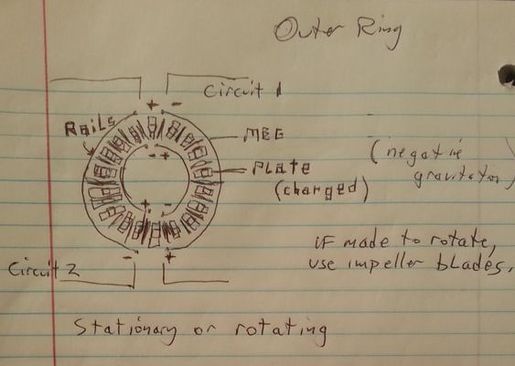
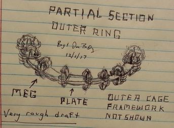
This is an idea, and the rotor can somehow be employed to generate a field much the same way as the OTC-X1 motor (or the Alexey flying machine device for that matter), so that the Outer Ring picks up a negative energy field.

. . . 

At about a net total of 725 watt power generated on their own (the input power is subtracted in that number), getting a whole bunch of them working at once is sufficient power for an electric inertial impeller warp drive.

​Solution.   See the  Free Energy / Tesla  page for details about the MVP.


The reason the MEG isn't viable, is because it is not AVAILABLE.  It required a special nano-crystalline core block, which only about 20 of those blocks were ever made.  They were promptly taken off the market after reported success by Tom Bearden and his associates. 


​


0 Comments

Outer Ring Problem; Resonance Pulsed Transformer

7/24/2018

0 Comments

 
The outer ring MEG version is not making it.

After considerable research of the MEG, it is not conclusive that it is a viable or reliable source of power production.  Also since Dewey Jones has disappeared, the Outer Ring project is dead in the water, and may have to be eliminated altogether in the LAU-X4 design.

The vertical impeller is still viable, and the OTC-X1 is still viable and is currently being developed, but very, very, very slowly.

So the LAU-X4 is down one engine.

It's a good idea, as a field generator, but as the OTC-X1 development project has come along, the outer ring has acquired some issues in that it is using too much positive electromagnetic energy.

The LAU-X4 may not require the Outer Ring engine at all, as has been stated before, whereas resonance coils may be able to replace the system, and vortex coils may be able to replace the system depending on how they respond to magneto-electrostatic input.  

The overall field flows will work REGARDLESS of there even being an Outer Ring engine.


What we do know, is that we do have a viable power source using the Bedini MVP pulse motor; whereas a ring of those will create more than enough power considering all it requires is 50 watts input for 772.5 watt output ON JUST ONE UNIT, which can be looped through the entire system OF AN ENTIRE SERIES OF THESE DEVICES.  So 40 of these engines set sideways, each individually measuring dimensions of about 2 feet by 2 feet by 6 inches, stacked around in a ring would create an output of close to 30 kilowatts.  

The only problem with this, is that it would not be in the right position to put these generators at the perimeter ring of the LAU-X4 craft.  Although in the internal "crew space," it is just fine for them to be there, and output from the generators can nonetheless be fed to an Outer Ring field generating toroidal system, and even a rotating magnetostatic pulsed resonance transformer can be used on the Outer Ring.

The resonance pulsed transformer is basically a resonance coil, in segments that pulse and loop magneto-static charges around the perimeter of the Hull, based on Tesla's rotating AC charged hull plating.


So this represents a step back to an earlier concept.

But at least now we finally have a working and demonstrated power source that can be self-looping, with excess high voltage flyback serving to power the internal systems.  I do like the concept of the outer ring, but we have definite validity in the OTC-X1 and the Townsend/Brown plasma dynamic dielectric setup with the vertical core and hull layering.

These all need to be tested obviously, but the physics aspect to these things have reached a point to where things just have to be built at this point.  But this is the status of the Outer Ring.

It does not mean all is lost, it just means that now the only direction left to go is to build the systems and go from there, and the Outer Ring can be adapted and applied as the development phase gives us definite knowns about how all these systems work, starting with the OTC-X1.


Regardless, we're at a real starting point with a real working technological basis.  See the Construction Blog page for the test setup of the OTC-X1.


​


​


0 Comments

Marko Rodin Outer Ring Alternative

7/6/2018

1 Comment

 
This is an *interesting* article . . .


The only other option for the Outer Ring as a power amplifier is to use the Rodin Coil, and place many Rodin Coils within the Outer Ring, replacing the MEG concept.  

So all the individual MEGS can be replaced with individual Vortex coils.

This would also explore negative energy characteristics through the power amplification that the reactionless Rodin coil provides.   Power amplification and overunity energy is another characteristic of negative energy.  Another characteristic of negative is its healing effect upon biology, also demonstrated by Rodin and vortex coils.


The MEG is actually really unknown.  There are a few old videos of it from 5 - 10 years ago online, but it may very well be a viable negative energy solution.  However Marko Rodin's coils have also been seen to demonstrate reactionless capability, self-resonating capability to continue to output power 5 minutes after the power source was disconnected, and Jamie Buturff of Sedona has also demonstrated power amplification in a Rodin coil, using 3 separate circuits, of 3 separate frequencies that play a musical chord at the Pythagorean perfect note scale.

Jamie Burturff's work can be seen on the Warp Drive News page lower down on the page, but there ARE many videos of Marko Rodin's coils that are actually working.
 I would surmise, they would work with negative energy involving the electromagnetic collapse being run through the coils for a magneto-static field effect.

The static force can be conducted through insulated magnet wire, and at high enough frequency, through insulated power lines (as Tesla discovered when working for Edison on the old D.C. power lines).


​
One thing though:  The Rodin coils all set around the Outer Ring cavity (which is a resonance cavity), would seem to induce a dynamic flow in either clockwise or counter clockwise motion of spin.

They would have to be charged magneto-statically however to induce gravitation (magneto-electrostatic inertia).*  (untested)  

The two directions of dynamic flow would be in the same direction as the outer shell of the OTC-X1 engine, or in the opposite direction.  This would seem also to mirror John Searl's style, which would be most logical to spin the dynamic flow in the outer ring in the opposite direction to the outer electromagnetic peripheral frame of the OTC-X1 (its hull).  This would also accommodate the matter-plasma flow from the vertical core, creating an acceleration instead of stopping and suddenly reversing the direction of the flow.  

Regardless, using individual Rodin coils for power amplification (instead of using individual MEGS) would be better able to affect dynamic spin of the Outer Ring (dynamic flow spin within its resonance cavity).  That aspect is discussed elsewhere in the website.  

Even though spin is used in engines such as the OTC-X1 and John Searl's SEG magnetic saucer, it wasn't used in Townsend Brown's experiments.  Although in lifter tests, a lifter spinning on a gimble was stopped when the lifter was turned on (a gravitational / inertial shift, the only force that can disrupt a gyroscope other than an applied counter-spin, of which the lifter does not spin when it levitates).

It might create a vortex flow.  It actually may be appropriate to face all the Rodin coils in one direction on half of the Outer Ring, and then face the other half of the ring's Rodin coils the other way, but maybe not.  I'm not really too sure about this aspect.  I know it will amplify power though, and would charge a central wire running around in the center of the Outer Ring, running through the holes of all those Rodin coils would energize to extreme volts (and amps too, according to some experiments I've seen).  It may not create an inertial spin inside the Outer Ring, which would be just fine with me!

NOT inducing an inertial spin, but instead inducing tremendous electrical charge would be much easier to work with.  

I'm not shooting for an induced spin in the Outer Ring, but I'm looking for an amplified charge to power the other engines, and to create a pathway for which negative energy can be conducted as a static field, using Townsend Brown / Tesla technology.  The Rodin coil fits this role nicely.

The MEG has its place, too.  It backs up OTC-X1 physics, and Tesla physics, and engineering.  The Rodin coil would do a similar job I'm thinking, because it would be allowing for field collapse to the center of the outer ring resonance cavity that creates a higher output than input, which is another basis and characteristic of usage of negative energy.  This is actually the basis of Dr. Harold White's initial research in creating a warp drive bubble, was to use vortex toroid-shaped coils, if I'm not mistaken.

Reactionless drives in this sense of the Rodin coil were heavily looked into by the military and defense departments, according to Marko Rodin who said he worked with them to show them the technology.


. . .


This represents the only technology we currently have available that is not suppressed or classified.

I've put a lot of work into this website in order to understand what we have to work with, and what the physics would look like to show a successful FTL drive or craft; and it has taken me some time to accumulate as much evidence as possible to account for viability.

​

Resource to a monopolar electromagnet similar to a vortex coil (monopole is characteristic of negative energy):

http://www.rexresearch.com/lorincoil/lorin.html

A magnetic monopole is as easy as clicking the north end of a bunch of strong magnets to a steel rod, whereas the steel rod becomes one monpolar north pole magnet.  That is also the type of thing going on with using dissimilar metals in an Earth battery setup (relates with Tesla Ley-line).


. . .


Personally, I *REALLY* think you should take a good look at Tom Bearden's website:

http://www.cheniere.org/


There is a provision in the  Constitution of the United States  that suppressed patents MUST be released after a certain time, and I quote:  "Suppression of free energy technologies violates Article 1, sec. 8 clause [8] of the U.S. Constitution which mandates the progress of science by disclosure of discoveries of a limited term"

http://www.cheniere.org/misc/USConstitution.htm#patents

​

The MEG (Motionless Electromagnetic Generator) DOES work; and Tom Bearden worked with John Bedini as well.  Both the Bedini brothers died on the same day at the same time, and Tom Bearden might have also been killed, er ..  I mean passed away as the rumor-mill says things, but I'm hoping there's a Mandela effect with the timelines going on here and he may still be alive.

Regardless, there is about 20 free energy devices, and multiple patents on Tom Bearden's website so well put together and thorough that anyone can duplicate MANY of these overunity and zero point devices, on his website.

The MEG was granted a patent, and independently verified by peer review and by other researchers:


http://www.cheniere.org/megstatus.htm
​​

The MEG is probably one of the most suppressed inventions in the world struggling to peek out into the public realm.  My mentor's MEG (I personally witnessed) took a little start-up power, but then power from the battery only powered the timing circuit from then on out.  It produced 750 watts, and it was pretty small, less than half the size of a small toaster, maybe as small as 7 inches long and 4 inches tall, and about 4 inches deep. 

It's self resonating, remains on for about 5 minutes after the power is shut off, JUST LIKE THE RODIN COIL! 


​

Here are the unwritten rules which apply to free energy:


1)    Keep it private contract.  Don't tell anyone, don't teach anyone, and don't connect it to the grid.


2)   If you're gonna talk, put a battery somewhere on the system, as plausible deniability.  So if a battery charges up 10 batteries, then it's considered "overunity" instead of zero point.


3)   Connect it up like you would do a solar or wind style setup -- use batteries, capacitors, etc, just so it LOOKS like it's not really all that special.


4)    Keep it on private property to use it, and don't use it out on the streets, and not in city limits if it gives off an energy field.

​
5)    If it floats or flies, that's bad.  BUT, battery-powered warp drive MAY be allowed . . . 


Of course, if you don't tell anyone, there's no way to establish vested interest, or to exercise free speech, or to live as a natural Human being, evolving in these times.  If you don't teach anyone, then what good is telling anyone, and what good are our university systems, anyway?  We've worked the planetary environment and economic systems into a hole as it is, and our knowledge level FAR surpasses the necessary technological level we should be at.  There's no way to stop a Human being from thinking and being the tool-making explorer that the Human being is.

Private Contract is a good idea, according to Article I of the Constitution, government cannot impede or interfere with private contract.  Also the suppression of technology, discoveries, and scientific progress was used in the dark ages, so the Constitution recognizes this threat of keeping people on Earth (be it Human or otherwise) in ignorance.  It is against the law to suppress scientific advancement, or to impede others in that area by theft or threat or otherwise, and to violate people's lives, liberties, property, and pursuit of happiness.

Suppression of technology has a limit of term, and eventually must be released and revealed.  This is a volatile field to be in, where natural ways to produce energy are being discovered left and right by EVERYONE.  People are smart, and that's the whole point.  I may chide people from time-to-time, because it's a little frustrating that people are not taking responsibility.  However I see more and more where people ARE taking responsibility to be co-creators to the planet.

The threat isn't the public.  That is the safest place for free energy.  Suppressing it, and antigravity is due to the threat of the politicians, bureaucrats, and governments that seek to control everyone's lives and take away the natural unalienable rights of intelligent people to exist.  That's why the suppression, is because in the hands of governments, they would wage trade wars and economic warfare and energy wars upon the people.

Granted the other hand of this is that the public CAN be a threat due to the ignorance that the public is kept under.  Ignorance is the purest form of evil, because people's lives touch other lives, and touch the lives of the biology of the planet; and consciousness affects the life force flows of living biospheres, including in living beings.

Get a REAL education, as is your natural law right and responsibility to life.  

​


1 Comment

New Outer Ring Framework

11/27/2017

55 Comments

 
Negative Energy Framework                                                             CRITICAL UPDATE:  12/03/17
​

​
I've decided to use a style of Townsend Brown / OTC-X1 hybrid for the outer ring assembly.

The Outer Ring's function:

1)  Negative energy field generator

2)  Negative energy power output ring

3)  It can spin or rotate, but is preferred to be in a fixed position

The Outer Ring provides power and flight stability, and field stability -- extending the field resonance from the OTC-X1 to the outer perimeter of the ship.  It is a "field resonance" ring.

The Outer Ring is powered by many MEG-style devices (motionless electromagnetic generator) around the ring.  Motionless is the key word, here.  

Various coil assemblies can be used, as well as several different mechanical timing circuits; wiring-in-series; vacuum tube diode bridges (instead of solid state; the vacuum tubes have a little spark in them, so it's compatible with negative energy); and hemispherical circuit architecture.

​


This is a better framework, using di-electrostatic plates between MEG "heads."  Internal "super permanent batteries" can be used to add that little bit of energy to the MEGs to start pushing it all up into vacuum resonance for high frequency and wattage output (providing power to the whole ship, including extra power to the OTC-X1).

The circuitry and commutation and polarities from the energies can be much better regulated if the ring did not move!  The segments and sections also can be grouped to hull charge plates (for better stick and rudder type of maneuvering, and/or better power regulation).

This is just a basic framework, but is more logical than using coils in this instance.  Also, this is a fixed point of reference. There's enough rotating parts inside the ship that a fixed point of reference would be welcome, since the main hull is not going to be spinning around, but only the lower part at the OTC-X1 engine.

Also, since electrogravity plates can work in a hard vacuum (​https://arxiv.org/pdf/1611.02576.pdf), then there need not be rotation for the charged flight surfaces, particularly since the charged flight surfaces would cause the ship to rotate left or right and be steered -- much better handled from a fixed point of reference.

​

Picture
This is a top-down view, although not to scale. The megs are represented by the radial hash marks, and the plates by the squares.

​
Picture
This is just to give you a rough idea.  There should be a little space in between the plates and MEGs, just like there's space between the capacitor plates and the utrons on the OTC-X1.

The plates intersect the zero midpoint of each MEG (they're in the middle).

The outer cage framework, shown in the articles below, fit around this assembly.


Negative energy field generator and power generator.  Same as OTC-X1, but motionless, and without central core.  The impeller is the outer ring's central core.  

Di-electric plates resonate with magnetic current between MEG central cores.

"power steering" for the impeller.


​

~ . ~ . ~ . ~ .
​
​

​
​The MEG is oriented vertically as seen in the image below.
Picture
The MEG adapted for use in the Outer Ring. Central resonating magnet. Outer oscillating electromagnets (as one collapses, it fills the other, and cycles; so technically it is AC to work more efficiently. If Tom Bearden made it in DC mode however, then it's a piece of cake to integrate into the LAU-X4. Otherwise, a negative energy-based wiring harness will have to be used to isolate DC from AC, and with a precise sine wave, ideally.

UPDATE ON THE MEG:

It appears that the MEG actually is in DC configuration.  The coils create an electromagnet in the same polarity as the magnet in the middle, the reflective magnet.  The static energy from the coils mesh with the magnetic field at right angles; rectilinearly. When the electromagnetic field collapses, magneto-electro-static energy waves are transmitted at right angles to the alignment of the north-south pole, in parallel to each other. The electric-static field fills the "spaces in between," moving in the geometry of the "disintegration of mass," relative to the magnetic field, essentially fitting like gears, together.  However you want to look at it, the central magnet resonates with each hemisphere; and when the hemisphere switch to the other coil is made, the central magnet is still vibrating with electrical energy, held in the magnetic field -- because it holds and transmits and resonates electrostatic longitudinal and parallel waves, through the magnetic field.  This actually causes the magnetic field to move faster than its waveform allows, too, because the magnetic field, separated by two most distant points will conduct through the electrostatic medium, giving the electrostatic field a MAGNETIC quality.
Picture

​If you look at the drawing of the MEG Outer Ring segment above, the central magnet carries its lines of flux around the bubble in the most efficient way possible.  So from a point in the middle central magnet, to a point on the outside edge of the field, between those points longitudinally, magnetic energy will conduct IN BETWEEN energy wave crests, in-between the troughs of the sine wave, breaking the continuity of frequency (time), and effecting everything that vibrates with electromagnetic energy (all matter) in the vicinity of its negative energy field.


​

​The energy will still cycle for a few minutes when power is shut down to the input of the MEG.  As a load is applied, in particular an inductive load, then the MEG will respond by increasing its output, as more energy is drawn from that vacuum.  The magnet will accumulate electromagnetic energy volume, and the mass of electromagnetic charge, so it is a radiant energy source that can be drawn from, for power, due to the vacuum collapse of the electromagnetic field --  the collapse of electromagnetic field space, which is a negative energy of electromagnetism.

This makes it infinitely easier to wire the Outer ring MEG to plate connections (the plates are horizontal, in the middle of the outer ring, in between each MEG).  


​
​~ . ~ . ~ . ~ .

​
​​
Picture
Picture

A rotating static field around the perimeter of the ship can regulate the flow of electrogravity charge around the hull; it doesn't have to be rotating, but can be just static charges, for simplicity.


These are various notes, I particularly wanted to note the hemispherical type of circuitry and geometry that the SSP also uses.  Rotation can still be achieved by rotating charges through a cage, or through disks or half-disks around the outer ring space, but the hardware should remain stationary, otherwise it won't be any fun to wire up a complicated rotating engine.
​
Picture


​Charge orientation and circular field flow is divided in half, otherwise there would be a start point and a finish point at one point around a circle that breaks resonance.


The di-electric plates can actually double for capacitors in this case.  The MEG uses vacuum technology, and so the ring itself is a negative energy field generator.  The magnetic core however accumulates more of the bulk of the negative energy charge, like the OTC-X1.  The flat plane where the plates occupy, around the disk, is geometrically aligned with the MEG "generator heads."

I'm trying to get away from requiring the outer ring to actually spin, because then a lot of variations can pop up, and a lot more variables and unknowns.  If required to spin a north/south magnetostatic field, that can be done through field coils, rather than attempting to move the whole assembly.  Also, it would make it easier for testing, to just spin field polarities, instead of actually spinning hardware.  

To elaborate on that, the only way to spin the outer ring is to use magneto-static fields, since to use electromagnets would destroy the negative energy field shape by introducing positive energy in the ring.  So, making it a physically-rotating assembly is out of the question!  Also, if using large magnets, then it defeats the purpose of using the OTC-X1.  This outer ring powers the "warp core," the vertical impeller engine, so the field shape needs to already be established throughout the ship at that point, and the outer perimeter of the hull needs to be using only negative energy.  (the rapid collapsing of electromagnets is a frequency of negative energy, so the MEG and the OTC-X1 electromagnets do establish the outer edge of the field itself)

The outer ring will generate more power, the more of a load drawn -- that is a feature of a MEG, and likewise most negative energy generating technology, including the Tesla tower Ley-line

(the land-based system -- Tesla tower Ley-line -- will pull a constant current flow on a load, until that current is broken, then the power isn't there anymore until the system charges back up and spins it up again; in the new configuration this problem will be avoided, but it's very similar to Keshe's Mag-grav generator, at least the earlier models).

Negative energy has certain characteristics.  The Outer Ring can also charge the OTC-X1 central accumulator more, not just through the impeller, but independently, in case the OTC-X1 needs more of a high-powered field to handle the extension of the hull past the OTC-X1 electromagnets.  


The purpose of the outer ring is to generate power, and a field, but also mainly deal with static fields, and/or rotating static charges around conductive di-electric plating.  

A "static ring" like this should be more than adequate.  If it just requires moving magneto-static charges, then the impeller can be simplified, so that a charge moves along the conductive surface, instead of the conductive surface suddenly generating a surface-charge -- sending a moving charge along a rod, for example, is more valuable than sending a moving charge through a series of plates, to simulate a movement of charge.  A full sine wave is more desirable than a broken imitative sine wave.

Since John Searl's craft shut off a section of charged hull to steer his craft, then I'm thinking a non-moving static ring is the next step toward simplicity and power, and electrogravity warp drive.

Having the outer ring broken into segments also won't confine the OTC-X1 operation.  A craft that doesn't have to gyrate or spin, to fly is a solid foundation for a variety of electrogravity or antigravity achievements.  It if can be handled through narrow plates, then craft don't have to be big and bulky.

​Air / plasma is free to flow through the outer ring assembly through the inner hull air space.


If it does have to rotate, then using rail-gun style or other magneto-static style of rotation to spin the whole assembly could be a very useful thing to do; but if we can avoid that, then it would be better for testing and experimentation.

​
​
I think this simplifies this whole system, now, so it can be something that can grow from here.  It's a bit unusual, but I don't think the plates in between the MEGs have to spin or anything (like a Dr. Ning Li device), because the Townsend Brown di-electric does NOT have to spin, and it has been seen to work.  Is it the most efficient?  Not necessarily, but the hull is a solid non-moving shape.  Adjusting the magneto-static field around the ship is a great way to move it around, and it doesn't have to be openly exposed to air, but the high-volt charges can be behind a ceramic outer-covering, that still conduct the magnetic field (magneto-static field), but without a high-volt shock or discharge that can short out parallel plates.

There's other styles of antigravity, like David Sereda's design, which was confirmed by tests in a French lab, but this (the outer ring) has the least side-effects and environmental disruption or destruction (no ill effects to the environment).  A single MEG can generate enough of a static field conducted along surface plates to easily lift a small light-weight static air-frame for testing and remote-piloting, which has been done by my mentor, years back.

So, this is a fairly valid concept.  I wish more coils were involved to give the outer ring more resistance so it can power a stronger load, but it is expected to generate AT LEAST tens of thousands of magneto-static volts, with corresponding high amp output.  What makes for good power steering at high speed flight is a good static ring around the ship, to change the electrogravitational forces and negative energy densities.  Bob Lazar's ship worked with an electrical plasma field conducted around the hull, but it was radioactive, and wasn't ET technology -- it was German from WWII, from Victor Schauberger's Haunebu III.

Internal transformers and mechanical timing heads would have to work in tandem with the outer ring, too.  This is one of the original ways Tesla had achieved antigravity or electrogravity levitation, by just using static charges, or rotating static charges around the hull.  

The outer ring follows a Tesla / Townsend Brown style of hybridization. 

This is the basic framework for the Outer Ring assembly.

​
-->   See the comments to this article, too.  ......


​


​Vertical Impeller and Outer Ring Update:

Picture
The outer ring orientation now is different, so that the electromagnets align vertically, instead of horizontally across the top and bottom. See the above content. I'll eventually get around to making these changes in much better diagrams; but for now, this is how it is.

​
I'm going to transfer some of the comments to the main article...  Sometimes I do this, but sometimes I leave the good stuff in only the comments.


​
New Outer Ring framework. 

The framework is a lot like the core. If the core is complete, then the whole thing can be derived from it. Improvements can be made, but the core will always be the same.


The simplest form of electrogravity is to align magnetostatic charges in a surrounding negative energy "warp bubble" as they are calling it these days. This will do the job and power the main engine, and power the "flight surfaces" for maneuvering and "power steering." The ring is like Iron Man's but way different. Lol ... it also floats.  It will float because it's a negative energy field, not because the plates push it or pull it.


Basically (in the MEG), the magneto-static resonance is an active vacuum resonance, vibrating between the outer oscillating electromagnets and the central magnet. It creates the negative energy field and tremendous power output without any moving parts.

Some MEG systems also are able to output 5 or 6 hundred times the input.

Special battery construction will be included, for permanent batteries. However through a self-oscillating system, which builds itself up and up and up, the power output will far exceed the small start-up energy from a permanent battery electret.

The trick there, is to use the output energy from one MEG to power the input of another, and cycle it through itself, while pulling a load such as charging plates. Likewise with Bedini systems, batteries can be easily managed.


It is also possible for the plate construction to be layered metals sandwiched between dielectric electret materials as batteries to power the MEGS, and to conduct magnetostatic energy across and through the plates.  
In fact, this is much more logical, and with a magnetic plate layer as seen in the link in this article, the magnetostatic field can gain additional resonance in negative energy. This way, the outer ring can be self-powering and conserve interior hull space. I like this idea. It's like a Tesla tower Ley-line, in a circle.


The vertical impeller can also churn up a static charge in the cylinder housing for motion. If the impeller also uses T. Brown plates too, then it's a double whammy. ... the concept of the vertical impeller itself is pretty easy to grasp. I had visions of such a system when I was 8 years old. ... if anything new about it comes up, I'll mention it .. or just save it for a much better organized and simplified book which will include the permanent battery designs.

When you include an inertial resonance and frequency, with the magnetostatic impeller, within the resonance cavity of the central vertical core, then you've got compression at one end, even better than the cone-shaped EM drive. Not to mention the negative energy mass plasma/particle flow that the warp drive engineering page talks about. 


Obviously, you can look at the MEG as a negative energy Transformer, which transforms positive energy into negative energy.

Of course now with the completion of the OTC-X1 physics, and the outer ring design, pertaining to negative energy inertia, the outer ring provides that zero inertia field the Warp drive engineering page discusses. It's done thru field correlation and magnetostatic vortex dynamics. 


It makes it a lot easier than using heavy exotic mass rings. It's the same principle, but instead uses negative energy physics instead of Einsteinean physics.

It's an easy switch to flip from positive to negative ENERGY. Positive inertial gravity to negative energy gravitation. Metallic hydrogen would be a good thing to try as the conductive exotic plasma/gas. 


This is difficult to work out a pure form of vertical impeller physics. Drawing a magnetostatic active vacuum is the easiest way to describe it. You just gotta remember we're not dealing with positive mass frequency anymore. Understanding it becomes easy and intuitive after a while. That's the ideal place to be in one's knowing.

The scaler longitudinal wave carries an electromagnetic energy much faster than its wavespeed. So you are compressing negative electromagnetic "time" in the vertical engine core. That is literally an ANTI-gravity impeller. 

The outer ring specifically deals with the warp drive vertical engine and field shape. So it is relevant to discuss the impeller in this outer ring article.

​
Hope you can forgive my crappy drawings here in this article. The plates are centered in the middle of the ring like the OTC-X1 plates. Centered at the intersection with the MEG zero magnetic point.


Keep in mind, the vertical impeller pulls the ship up, as seen in the orientation, in the image above.  It doesn't create a "thrust" reaction, but instead it draws a "vacuum electrogravity."  It's the same effect as perpetually falling into a pocket of gravity above the ship, similar to how Viktor Schauberger did it with the Haunebu III (Bob Lazar's famous "element 115" back-engineered craft), but very different -- without radiation or positive energy forces, or energy losses.

​


​

Adding more of the comments:

Be sure to check the comments below, however, for the double-coil method for tuning a magnet, and other frequency secrets and Tesla public-domain resources.

I do want to share this, though:

​
​A single pole (characteristics of negative energy is just one-polarity) of electromagnetic current is run thru the scaler longitudinal energy field of the horizontal plates through the middle (of the outer ring) between each MEG. Cutting the wavelength in half, electromagnetic polarity can move in a straight line, and it cuts its time  in half ... when time is cut in half (the waveform of electromagnetic frequency), it breaks continuity.  If there is no continuity, time is not defined. 

You could say the electromagnetic wave cuts ITS time in half, but that's going to carry a frequency of time throughout all things that have electromagnetic frequency, which is all matter.


~ . ~ . ~ . ~ .


​

Unified Proof of Concept and Negative Energy Unity within the Framework of All LAU-X4 Engine Physics:


Gonna pull more comments out and organize this into the article, so hopefully such a general framework of negative energy unity can be easily referenced all in this one article.

I'm going to organize this into parts:


​​
​
​
General Construction Details:

because this is perhaps the most complex engine of the ship .. you CAN use a spark gap like a diode so that only the electromagnetic collapse is carried to the plates, excluding the positive energy electromagnetic "fill" of forming the magnetic field in the coil. (wiring only for negative energy)

That worked successfully in my Tesla tower system in fact. 

I've had the benefit of seeing the MEG actually work .. and have exposure and experience with this technology. It's not as hard as you think. The MEG has easy input/output terminals. Tune it at 42 megahertz. Tune the magnet to the same (the double coil method). I explained that somewhere in the comments.. otherwise, it will still work. Just play with it.


The shape of the MEG can be modified a bit so that the coils are wound around a straight section of the ring, because winding coils around a ringed shape would be a really poor coil, and we can't have that, with the increased power output from the new frequency tunings.


​


The Double Coil Method for Tuning a Magnet:

Resonance coil. Stand it vertical. Put a stick on top, set your magnet on top of the stick. The resonance coil has AC frequency going to it. The magnet will want to fall down. When you hit the resonance frequency, the magnet will vibrate back and forth but will stay balanced on the stick. 

Now drop the magnet down the coil and rest it on top of another coil (coil 2). With coil 1 running at set frequency, hit coil 2 with 42 megahertz, just a quick pulse. 

Tuned.

My mentor taught me the double coil method.  42 megahertz is the baseline frequency of our local star system; rather baseline frequency harmonic in resonance with the galactic core. 


Tuning your Coils:

Another frequency secret.. once you know your magnet's resonance frequency, you can tune your coils to that frequency. Tesla had a rectilinear approach to that. If you know a wave frequency, you can make a loop of wire that matches the wave frequency. The wave has height and shape, and you can graph that to determine the size of each loop of a coil (diamete, circumference, number of loops in a linear distance that equates to resonance harmonic of the wave you want to receive) Take a straight wire, divide it in segments which is the circumference of each looped coil winding turn ... that same straight wire can be a single loop or multiple loops in a coil that measures the same as the wave frequency. 
​
Tesla's Colorado Springs notes are in the public domain now. Well worth finding! He gets into this in his notebook. He also writes about transforming matter and energy states. So ... this stuff is starting to get pretty interesting.


Engine Physics:

... also, as I mentioned on the Construction blog page, the MEG levitates when a large inductve load applied such as a large transformer - a transformer on the output line to a load (such as the electrogravity plates). 

That's how Tesla did it. The higher the frequency (using a Tesla transformer), the craft went from low frequency hover (green static color) to a fast travel speed (violet). 

​That is super important because the MEG under testing conditions only levitates when under large transforming inductive load. Actually, its the resonance load of the transformer, which is responsible for the MEG to ice up and levitate. 

Two Tesla transformers control the frequency of each outer ring hemisphere, of the electrogravity negative energy output to the the plates AND upon the MEGS. <--- Tesla transformer acts upon its energy creation, and its source.

So the transformers are between the MEG and the plates in circuit.  There will have to be enough room for transformers in the saucer aeroframe.  


​
This technology theoretically outperforms SSP heavy exotic mass ring technology, and provides more reliable field stability ... This is purely a biological field interface, "wirelessly" ... it is designed with compatibility to the Human energy field.
​
​Of course, power level adjustments and directional flight controls are part of the pilot interface. Pilot won't experience inertia. And the addition of the vertical impeller may make the journey easier to remember due to those field geometries. 

The outer ring may help stabilize memory issues too. ... that's a little too beyond the subject of this article.

The pilot must be conscious of the journey, traveling through discontinuing time with broken continuity. The pilot makes his own time, and all occupants must be aware if their temporal target destination. That will maintain a conscious framework thru temporal displacement.

I wouldn't leave the field on for extended periods of non-use. Don't push yourself beyond what you think or rather what you feel you can handle....


Artificial or on-board gravity:

It is assumed that the gravity field of the Earth is held in resonance as long as the outer ring is on, at least, or as long as the OTC-X1 is idling. Like how a magnetic field is set into a piece of iron ... but may become demagnetized or re-magnetized by sufficiently larger nearby gravity fields.


​

Negative Mass:

When the mass of the central magnet is fluctuating in positive and negative energy (considered exotic energy and exotic mass), which is caused by the scaler longitudinal wave from the collapse of the electromagnetic field coils to momentarily also collapse the central magnet's field (also this energy is conducted magneto-staticly thru the transformer block), then the central magnet itself converts to AC negative energy. AC negative energy is exotic.

The mass of the magnet becomes a negative mass in AC-negative polarity. .... that's where the vacuum energy comes from. The levitation of the MEG is electrically achieved by reducing the mass of the magnet to a negative electromagnetic value.  This is proof of concept. ​

When the magnetic field from the MEG central magnet electrically collapses, and then rebuilds on it's own force in rapid oscillating frequency, under those conditions is when the mass of the magnet is a negative value (negative energy). It's like Searl's engine.

​The alternating of positive and negative ENERGY is what I consider AC-negative or EXOTIC energy. Positive and negative form ...  <---  This is highly significant;  and is a requirement for stargates as well as hyperspace jump drives (teleporting in a series of very-long-distance space jumps, which is how a "beam ship" is described).
​


The vertical impeller:

It delivers a negative energy pulsing, a frequency beam of negative gravity. Do you see how negative energy leads to negative gravity? By changing the frequency of time, a gravity wave is produced. 

The vertical impeller delivers pulsed and spiraling gravity waves, specifically negative gravity waves, and in a beam due to the rectilinear nature of magneto-electrostatic geometry. This is the nature of tugging on the scaler vacuum, as these physics describe.


​

Electrostatic maneuvering:

Under negative mass levitation, the static force is what moves the ship. The static charge at one side of the ship pushes the ship in the opposite direction. That's how John Searl's craft moved. Townsend Brown's were very similar.  You can look at negative energy propulsion as "like squeezing a pumpkin seed in your fingers and it shoots across the room"  --  as my mentor has described it.

​Hull polarity too .. electrons flow to positive. And with negative energy, the energy amplifies flowing over an electrical radiant hull. 

The Tesla-tower Ley-line will put this system to the test, and has already proven results. So .. It's like the Earth's surface in a way, the hull is. ..

​
I want to note hull plating having a conductive magnetic layer and a dielectric and/or metallic conductive layer. And a thin ceramic insulative layer that can conduct a magnetic field (possible the outer skin may be the choice for the dielectric) that can conduct a magneto-static negative energy SINGLE POLE static current in the vacuum of space.  It will have to be insulative to touch, to keep plates from building up carbon and shorting out, when flying in an atmosphere, particularly polluted cities . . .  (Tesla wrote about that, too)


The higher the frequency of negative energy magnetic oscillation is lower field of negative mass. 

This is important. This is hull construction for the negative energy framework. A single magnetic layer will do because only one pole is being used.

Other plate structures like in the three engines will all be slightly different. 

I will have to publish those details.  Keep in mind, this has been published upon such Townsend Brown style flight in a vacuum:  ​https://arxiv.org/pdf/1611.02576.pdf


​


Engineering specifications and numbers:

​
When you think about how the vertical impeller can work .. the hull space can be charged for shielding ... just awaiting the impeller to turn on and start "churning up the static charge." .... The outer ring is supposed to handle those power requirements. At high frequency, not a whole lot of negative energy is required for this.

Considering the outer ring has a whole lot of very large MEG's, in a field-efficient core, with tuned magnet and coils, it's going to be a very large output, and will generate more power under load. 

I'd say about 70% of the saucer outside the cockpit area will be nothing but power systems, transformers, timing controls, battery/capacitors, etc .. But with enough area in between can house other equipment such as air-recycling filtration, water, circuit breakers, some pressure-vacuum tanks and pumps, spaces for landing gear, with very minimal space for crew needs like berths, head, and galley. ... at least that's what it looks like for a small craft.


Truly if all else fails with the permanent battery construction, which .. they're out there ... then Bedini systems can be employed to cycle batteries and/or capacitors, for sustainable battery systems. I'd prefer to go for a permanent battery, though. 

With the vertical cones engine, there was the possibility for the cones to also generate power, especially if applied to a Tesla / Bedini circuit. However, I believe the impeller to be faster. So, that would require permanent batteries, because there's just not enough room for much more equipment.

The MEG is PERFECT in this application .. and I do have a few ideas for permanent battery systems based on similarities with Earth batteries (again, working from the land-based radiant energy support angle) .. which actually some have been handed down to me, ... The polarities.. well .. let's say this will be handled later. The more powerful a permanent battery/capacitor is, of course the better. It would be nothing to see a 10,000 watt output from one single MEG from a small 12 volt, 10 amp electret (permanent battery). Those are the realistic numbers. Worst case, you'll see 1,000 watts from a 12 volt 10 amp battery.

Worst case is actual results from a rather surprisingly small MEG ... Just think of the resonance pumped up from larger units with more efficient core shape (eliminating eddy currents, and lessening the need for laminate material ... capable of achieving a much higher resonance) ...

Bigger isn't always better. Usually bigger equals more resistance. However, with a large enough power supply to drive the initial energy into the MEGs, then the MEG will drive itself and amplify. It's not impossible.


The power output of the Outer ring is in the general ballpark, from actual tests on individual smaller units is anywhere from 40,000 to 400,000 watts. That's with a power supply of 8,000 watts, of standard positive energy. So, weight can be reduced by using dielectret plates in the outer ring (di-ELECRET), and there's several places in the inner hull space for capacitance built up in "guide channels" of plate stacks for exotic gas flow (plate construction details will use alternating materials, to be released later), .... 


But also one MEG will create enough energy to power itself. So the battery weight can be very low, only needing about 1,000 watts to kick-start the MEGs into resonance. Like a starting battery. The only power needed is to run a timing circuit, which is a very tiny amount. Remember the MEG kept itself powered for a couple minutes after all input power was turned off, as I have said before, oscillating all by itself.  

Also, mechanical timing circuits (my personal preference) would not use much power, either.


Plate construction in the outer ring can use magnetic layers, in Tesla /Townsend Brown style; and since we know a magnet can create an exotic energy field, then we have a decent power system here.
​

When you consider how heavy John Searl's craft was, the OTC-X1 and outer ring are made for handling weight!  That is - a lightweight engine able to haul a good-sized weight load. 

Boatbuilding skills and knowledge work well in this application. 


​
The electrical energies will easily migrate to each system, if they are made to field-resonate with each other. Keep in mind there's open spaces between the engines - they are not closed systems individually. 

This means 40,000 watts is distributed with zero loss throughout the ship and holding that energy density on the hull plating. 100,000 watts should be a good target range to strive for, minus the energy output of the OTC-X1 (it generates its own power).


Vertical Impeller to OTC-X1 Hookup:


The OTC-X1 is the negative energy ground (will meter as a positive electrical-radiant, or electrostatic charge, OR apparently as the Construction Blog shows, the Central Accumulator should read as a north-positive, and south-negative magneto-electrostatic polarity, but will otherwise be a negative ground).

This allows for the top of the Central Accumulator to isolate a single pole.  The vertical impeller connects to the top of the central accumulator, either by lowering it into a transmission or otherwise, and also with the option of using a metal iris to open or close the static flow between the two engines.

Originally, the top of the vertical core contained a Tesla coil; that can still be employed, and I wanted to mention this in case it wasn't too clear.  

The vertical impeller connects pole-to-pole the Outer Ring to the Central Accumulator.  Now this is where it gets a bit peculiar:  The outer ring much complete a circuit through the vertical impeller (a return path from the bottom of the impeller to the outer ring), however the OTC-X1 completes the circuit with the Outer Ring, connected by just one pole.  The return path of electrical flow is completed through the negative energy field.

A little resistance can be added here by making the return path from the impeller to the outer ring through only the plasma/exotic gas inner hull circuit; likewise, the Tesla coil up top initiates the flow through the vertical core.  With added resistance, negative energy will flow more superconductively.  

My point is that the impeller acts as an antenna to the central accumulator.  There will be engineering details of the top connection to the impeller later.  It's just a toroid field connection to a vertical shaft.  

In this sense however, there can be some separation between the OTC-X1 and the outer ring; however any more details at this point is going to impede the overall framework ...  I want to emphasize the separation between the outer ring to the vertical impeller, as this circuit is purely connected via field induction.


The bottom of the central accumulator can connect to the hull plating, and complete the connection through the hull plating to the outer ring (in addition to other connections to power the hull plating).  This should be hemispherical.  The bottom of the central accumulator to the outer ring, through that section of hull, and then from the outer ring to the top of the impeller, through that section of hull, these return paths can take such a route.

Connecting the impeller through one-pole to both outer ring and central accumulator engines, is a characteristic of negative energy   . . .  This also means that as the energy runs through the pathways, more energy will be generated, and in resonance.  The frequency of the electrical currents are also part of the resonance harmonics.


In warp drive full speed ahead mode, the outer bottom hull plating between the OTC-X1 and Outer Ring will tend to resonate more, as far as the energy static characteristics go (the outer ring and OTC-X1 will resonate through the hull plating circuit and build up energy thus).  However, the outer hull plating from the Outer Ring to the top of the impeller will be directional, and a current will flow quickly.  

That may seem weird, but since the Outer Ring is electrically anchored to the OTC-X1, then the Central Accumulator acts as a common ground.  Resonance will occur between the two energies and fields, even though a current flow through the outer hull plating may be directional, as well.  This resonance can be seen like how a Tesla tower creates earthquakes in an area, as the energy resonances with the Earth surface, even though current may flow from the ground up through the tower.  

This also enables the vertical impeller to act as a receiving antenna, not just receiving energy from the outer ring, but also from the universe and space that is in front of the impeller . . .  and again, the outer ring is functioning as an accelerator. 

^---  This.  ~.~.~  This is where the active vacuum is drawn through the receiving antenna, pumping up the Central Accumulator to the "electrical water chi-bubble" feeling of how energy gets when it does that.  This is when a WHOLE LOT OF ENERGY is produced.  

​THIS is how the vertical impeller also generates energy, or acts as a generator -- through the acceleration of the active scalar vacuum.  (It *IS* a scalar  vacuum)

​
​This completes the core design of the LAU-X4 hyperdrive starship --  By:  Administrator, Drew (12/03/2017)


~ . ~ . ~ . ~ .


​

Afterthought:  

AC MEG connection, just because it's too easy.


AC negative, which is the alternation of positive and negative energy (exotic), can be in either DC OR AC configuration.  The principles in physics will still remain the same.  


​AC mode actually can be used. I just want to make a note of this. Doing it this way would evenly distribute energy to the ring and plates; and the same principles of physics would apply. This would be a huge dynamic ... the static aligned north/south magnetic field would be transferred to the plates, while the MEG central magnet flips; the magnet could act as a diode (or gate), but it holds a stability of alignment within an oscillating and alternating frequency of collapsing electromagnetic currents. 

Similar to John Searl's in a way...

If you can see how it works in DC, you can see how it works in AC. it's not hard.  The north south poles on the top and bottom of the transformer core would be flipping in negative energy polarity, around the permanent central magnet, while it also acts as a diode to keep the left and right hemispheres in resonance, or otherwise allow current to pass only on the top or bottom . . .    

Like I said, it's a huge dynamic.  There's publications from Tom Bearden about the MEG, which should explain its operation.  

​

Another benefit in AC mode however, is due to the directional lines of magnetic force.  The circulation dynamics of the field flow have to be noted, because this is a real dynamic of a magnet.  The magnetic flow around the circle (over the surface of the Earth) should be from south to north, as measured from the northern hemisphere.  So this picture is backwards, but I'll use it as a reference, anyway:

​
Picture
If a coil on the left and on the right were wound, then one would have to be wound clockwise, and the other counter clockwise, to direct the flow.  Otherwise, they could be wound the same direction, but use an alternating current to obtain the same flow.  

Otherwise, an alternating current flow from coils in just a ring-shaped transformer block without a central magnet would oscillate a north/south pole on top and bottom.  So this magnet to the left could be flipping around upside down and rightside up, or RATHER, an AC frequency of negative energy can be applied to the central magnet which matches the magnet's resonance frequency, so that it vibrates and shakes with a large field output of combined magneto-electrostatic energy  <--- similar to how a magnet is tuned.  

​This is another way to harness energy from the vacuum.  

These same mechanics apply to the Tesla tower; and the energy harnessed from the active vacuum (free energy; abundant energy of nature) is static in nature, and can feel like "warm electrical water."  Also the same thing involved with the Tesla tower is involved with the plates.  

There's a secret involving AC and negative energy and massive power output, which also links to electrogravity that may or may not be this very thing here.  This overall framework certainly does make use of alternating energy phases.  


​
​
55 Comments

Outer Ring Defined

1/29/2017

4 Comments


​
                             What is this thing and why is it important, anyway?

​
Picture

                                       If you look at the outer ring cross-sections, you can see where air
                                       can flow around the outside of the transformer as well as through
                                       each hemisphere, so a static field can generate. That allows for
                                       conduction of co-counter rotational negative-static current . . .

​
​
   I think this system is fairly locked-in.    Minor adjustments to the hull shape, size and position may apply.

​
It's primary role is a capacitor / transformer ring, it distributes energy and generates negative energy, powered by a perpetuating spark collapse (considered a self-regenerating system; over-unity).  It plays more of a power system role.  I think it's too far away from the warp field generator, doesn't really have that much inertial value either.  ...  But it's a pretty big hull, compared to the size of the engines.
​
​

It can create a negative energy field but without any inertial value of its own other than handling particle flows, it depends on powering the electrogravity hull plating to distribute inertial energy which carries it along in the process. So it does make logical sense.

Without the outer ring, it would be difficult to tie in the three engine systems:  OTC-X1 warp field generator, vertical engine core, and electrogravity hull plating (maneuvering and dynamic propulsion).

​
It's not really a propulsive engine on its own.  It can be, but that's more of a side-effect of being adaptable, but it does drive the electrogravity hull plating because it's able to generate negative energy, with polarity, and a lot of it.  It doesn't mean other sub-systems can't easily be placed inside the ship however, but the outer ring handles the bulk of systems that could take up too much space otherwise inside the ship, and still be somewhat light-weight. The transformer/generator "heads" are a little lighter than the OTC-X1 electromagnets, in fact.

The only way it can reduce it's own weight / mass, is to use the hull plating to do so, whereas the OTC-X1 reduces it's own weight / mass in its motion.  If you consider the outer ring to be attached to the di-electrostatic hull plating, then it is very similar to the OTC-X1; but the outer ring uses the vertical core whereas the OTC-X1 uses the central accumulator.  The central accumulator doesn't necessarily create a propulsive gravity field in the same way as the vertical core and/or impeller, which generates a gravity field for forward propulsion (in that flight-mode).

If the outer ring includes a di-electric propulsive aspect, then it wouldn't reduce it's own mass, but it could reduce it's weight*

​There is the possibility that a negative energy electrogravity field similar to Townsend Brown's style CAN however reduce mass, or otherwise have that same effect to polarize mass as positive and negative, to affect movement, as has been discussed concerning the superconductive nature of negative energy involved in hull plating electrogravity.

Therefore, it helps us understand what's going on with the OTC-X1, by comparing the two systems.

​It has been considered that the OTC-X1 increases the frequency of time by using negative energy, thereby decreasing the frequency of the gravitational pull of Earth upon the OTC-X1, and also by harnessing negative gravitation.  Conventionally, it is possible that the OTC-X1 engine can thereby "lift" the whole ship for levitation, even with all the additional mass of the other engines and aeroframe.  Whatever is directly above the Central Accumulator, that additional mass of the vertical core is not a significant factor that hinders the OTC-X1's ability to hover.  The additional weight of the double hull adds some mass, but what really could be counter-productive is all the mass extending past the edges of the OTC-X1 lower engine system. The Outer Ring is probably right at the edge of the OTC-X1 gravity cancellation field.  But in order to provide room to test all these systems and to see how they all relate, and to measure what we have so far, the outer ring is definitely the "yard stick."

It is something to think about, and to test.

​I like it's dynamics, and the outer ring is not putting a definite north / south magnetic pole in a place where no pole should be, that would affect the overall field dynamics of the LAU-X class (no magnetic pole is sticking out like a solar flare; it's a contained loop).

What is definite about the Outer Ring depicted, is that it generates negative energy. 

That itself is important so the differences can be seen as to how everything works throughout a dynamic construction such as the LAU-X class. 

If indeed "all it takes" is just negative energy, as the warp drive metrics and mathematics show, then the Outer Ring is just fine as it is depicted.

​So, here's the clincher:

The OTC-X1 engine uses negative energy frequency to speed up time and reduce mass, and also give the vertical core engine more power, and more speed (electroGRAVITY frequency).  The Outer Ring is then merely a part of a superconductive framework, and part of the aero-frame, to tie in the fields of the X1 engine and vertical core.

​So as mysterious as the outer ring is, eventually the logic concludes that it does its job, however in perhaps a round-about way, but it does it's job.

We're only really concerned about just moving that outer ring around, because the other engines move themselves and that space surrounding them.  Since the outer ring is away from the other engine fields more, then it's about the same as creating drag. So everything is about moving that outer ring.  It would be nice if the outer ring collected the engine fields angularly that defines a space of a corridor in which the ship can travel, through that beam.  It's possible that it can, because it is at a place where all the fields terminate at the equator, and at the edge, in a ring of angular negative energy, catching and resonating the energy of the top and bottom hull-structure, at the edge, where that energy collects and builds and push/pulls the hull-energies.

​
So the outer ring is the mathematical solution involving negative energy which defines a space or bubble, where the engines can warp space and time allowing that space or bubble to travel according to how we expect it to do so.  It's doubly important because the ship-space is larger than the engines. 


I feel it important to successfully define the purpose of the outer ring, within the limitations of engineering design and physics.  What does it do?  Why does it work?  How does it work within the bounds of known reality?


Here are some general considerations:

​
If it starts to wobble while hovering, the vertical impeller (or cones) can provide some gyroscopic stability, and even generate additional lift, stabilizing the wobble of the vertical Z axis.  The outer ring will also work with the overall power system (adding it's own) to energize the vertical core, as part of its distributor nature. Particle flow between the core and outer peripheral is also electrostatic.  

Because the outer ring is located where it is, it will have to supplement the action, including adding additional energy to the X1 lower "warp engine."  That's the beauty of it being a generator.  Those particulars involved are details; but more importantly, those details can be handled in the "wing spaces" of the hull shape.  The details can be derived in the construction process; and, negative and positive energy can also be transformed.


Metalized hydrogen is a new development, which has been observed to be superconductive.  Such is able to be induced and to generate a field, I've been told.  The nature of the particle flow can be custom-tailored, much in the same way as the di-electric hull plating can be custom-tailored with various di-electric and magnetic material.  The outer ring itself can induce a negative energy field into a custom metalized hydrogen flow, for example, as long as it remains in a gas / plasma state.

Negative energy is a power source.  The universe also contributes to the negative energy source; similar to the concept of energy from the vacuum source. No fuel required, other than naturally receiving energy from the universe and building up, instead of dissipating like positive energy.  Positive energy can be "made" from negative energy; whereas negative energy is always created in abundance.

The outer ring as a field generator, not just through the hull plating but by its own actions, is better equipped to do so using metalized hydrogen for example in the engines.  When a negative energy spin is induced, then the material will be polarized with negative mass;  anti-matter, but without consuming mass in collision.  A warp field is a negative mass/energy field.  I know this can get confusing real fast, but the goal in this case is to use an inductive negative (magneto-electrostatic) energy field.  

Now the question comes up, why doesn't negative energy consume matter?  It doesn't!  Positive energy consumes matter. Negative energy doesn't heat up power lines, it builds up power over distance instead of dissipates, it maintains the circuitry it travels through (as long as the circuitry is built for it), preserves electronics and accelerates healing, and is the natural abundant energy of the universe.  However, negative energy will eat up positive energy superconductively. 

The only way negative energy will create anti-matter to be collided with matter is when a particle pair is in direct opposition, paradoxical to the "other half," otherwise negative energy can be run along a wire just fine, and the wire would be fine for thousands of years. A proton ion (without an electron) would have to be isolated relative to its matter/anti-matter pair, where the intersection (collision) forms light and energy.  In reverse, high voltage in a laser grid will form matter/anti-matter pairs FROM light and energy.

​This is also why it was brought up that the outer ring acts as an exotic mass superconductive light ring, requiring a particle flow in motion, which can allow the ring system to start reducing its own inertial mass and weight (weight can also be defined as a measure of resistance to inertial forces).

If you consider that the energy is applied to the electrogravity hull plating from the outer ring, and that the nature of a negative energy field creates a negative mass polarity, then we are talking about speeds greater than the speed of light, particularly between star systems.

Probably the most confusing aspect of the whole ship (at least to me) is the outer ring. It can do all that. It just has to have a little energy input to start it up, and to keep the system oscillating in time.

​. . .  and in fact it's not confusing, it's just a little complex, even though it appears to be a rather simple design. 
​
​
The proof of this also supports the OTC-X1, because the outer ring and the OTC-X1 outer peripheral is basically a very similar system.  That really says a lot.  It's all because of negative energy, which was recently made known to me about how to generate it, but I still had to work it out on my own. 

All the engine systems now have a solid foundation.  

The outer ring is the one system that links it all together, with the exception of the EM drive, as far as proof of discovery goes . . .  which shows that the OTC-X1 actually utilizes a negative energy transforming system at its peripheral, explaining a LOT about the engine itself, and about warp flight. 


​
​

​

Conclusive Simplification:


You may be able to look at it in this light: negative energy is why the OTC-X1 levitates (cancels its mass to zero so it has zero weight), and is itself what reduces mass to travel at light speed OR beyond. It is possible that warp drive really is just that simple. The OTC-X1 specifically generates negative energy, as does the outer ring. This is a severe simplification, but a solid implication.

This is to say that it is entirely possible, just as Alcubierre's warp metrics show, that indeed negative energy is literally all it takes to achieve luminal and superluminal flight.  Just as the universe will give energy to a negative energy current over distance, boosting it and pumping it up (transmitted over wire or wirelessly through fields, negative energy builds instead of dissipates as positive energy does), that is indeed possible for flight between star systems, that the ship will go faster beyond light speed as energy is created straight from the quantum vacuum.  Energy is received by the outer ring, for example, and/or by the OTC-X1 engine.  The outer ring creates a negative energy field that works with the OTC-X1 engine, extending the negative energy field (Tesla energy passes through solid objects, like how scalar fields can penetrate water and walls separating the inside and outside of a building).


An example of how scalar (longitudinal waves) generated on the land in a device can penetrate water to light a lightbulb underwater can be seen in this series about Tesla's Hair Pin circuit, whereas this is part II of the series where he starts to talk about it and it is eventually seen in the video series ...  I just rediscovered the video series, but I thought I had talked about this concept in more than just this one place:  https://www.youtube.com/watch?v=rNQkLhE8lHU


​
Energy created is energy that enters the universe, not through any quantum void, but through radiant Source-Creation Energy -- a Sea of Living Life-Intelligence -- the Creative Source Field.  Time crystals are a newly discovered form of matter which "actualizes zero energy."  Quantum energy is zero energy, or probability fields (which have zero energy), just as light.  The probability for energy to manifest creates energy. Energy already exists in an infinite state, but must actualize with inertia, intention, and purpose, form, as composite matter or otherwise, in the universe of energy -- that which is our universe; having energy to exist in the universe, or at least what we generally consider energy to be.  People are now starting to understand this.

Negative energy is the energy itself of negative scalar space, that when generated in a field or "warp bubble," that causes the ship to be able to fly at light speed and beyond light speed, without any special relativity limitation.  That is what Alcubierre's metrics do show, and why NASA EAGLEWORKS was created.  Sure, there's a lot more to the nature of negative energy; but as far as warp drive is concerned, negative energy is all that is required.

Energy is generated from the zero, expanded into the direction of its positive inertia (positive and negative mass), which gives the ship gravitational inertia and direction of travel.


​
It seems we are indeed looking at extreme simplification and unification of energy physics.  I really don't think that it is as complex a thing as this website makes it out to be, by severely breaking it all down to examine it under a microscope.  It has nothing to do with wishful thinking, either.  Sure, there is technique and form involved, but what it really boils down to, is that we can look at the technique and form to see how negative energy shapes and moves and works in ways that we have not known before.  Experimental results as well as mathematical validations do show exactly what we are dealing with, and have known it before in extremely ancient times.  

We can't exactly assume that positive energy reality is an illusion, but we must assume that negative energy is the true nature of the living, electrical universe of living light. One can philosophically quibble with that statement, so maybe it's better said that negative energy is the living nature of the electrical universe, and yet positive and negative energy work together to create form. Ghosts and spiritual higher dimensional beings either without mass, or with a unified light-mass, for example -- ghosts make cold spots of energy, whilst "gods and goddesses" or ascended masters can also be nonphysical.

. . .

When dealing with the impeller, it is somewhat opposite to the cones, in that it draws positive space into the negative scalar central accumulator (pulling space into the quantum vacuum in the direction of the beam, creating a true gravitational force "in front of the ship that the ship falls into"), pulling space into the scalar zero of mass, while the external fields take the ship out of normal space/time due to the negative energy fields generated.

Dealing with static forces and air/particle flows internally, the impeller engine can use negative di-electrostatic electrogravity energy, further reducing its inertia and mass, extending that field in a beam in front of the ship, affecting scalar space itself; the other end of the polarity is the bottom of the ship at the central accumulator, in an asymmetrical scalar shape. 


It's hard to say which engine would be faster, the vertical core of cones or the di-electrostatic impeller.  They seem to use different physics.

​


​


4 Comments

Di-electric Maneuvering

12/1/2016

5 Comments


It makes sense to use the Outer Ring also for maneuvering. Oriented commonly in the ways depicted here, which is shown in the first picture on the left, the di-electric medium would cause rotation of the ship "thrusting" either upward or downward, tilting the ship. 

Oriented in the way depicted in the right image would cause translation movement laterally say left and right.

These images are slightly off-scale ..  but it's enough to get the general idea, without giving away too much information, and also without limiting what creative designs can come after.
Picture
Picture
Picture

But since the Outer Ring is oriented as depicted in the image below, our only real option for the Townsend Brown di-electric is in a rotational value. A di-electric segment can be charged in one polarity or another to rotate the ship for example lifting up on the right side and down on the left side, and for allowing movement straight up and straight down. Once in the atmosphere, the hull plating can be electrically charged to provide movement.

Yet, since the hull plating is also using Townsend Brown style, then each hull plate section can be energized even in the vacuum of space to provide translation motion laterally (energizing those lateral plate sections on the edges), or rotational movement.

Considering that Townsend Brown's saucers were only about 3 feet in diameter and moved very fast (around 20,000 OR 200,000 miles per hour, I've heard both), it is an efficient system. Also the saucers were air-tight and completely cased / enclosed, which really says a lot.


The T. Brown di-electric did not depend upon there to be atmosphere, or air, in order to work. In fact, NASA is using di-electric orbital maneuvering and station-keeping on their satellites.  I once intercepted one of their electrostatic scanning beams over my Tesla tower.  It started out around 600 volts measuring on the console, but then went up to 1400 volts (if memory serves; I have that recorded on the home page somewhere). I googled "1400 volt electrostatic scanning beam" and it came back with one search item, the white paper with a part number, which was the satellite component.  

The satellite made a conductive electrostatic corridor between it and my tower.  When I grounded my tower, an "X" pattern would form in the sky overhead, like clouds formed instantly, telling me there was electrical interference waves due to a conductive energy corridor.  That put a stop to a lot of my magneto-electrostatic experiments, because I realized that I could have sent magneto-electrostatic pulses up the beam path which might have zapped the satellite, or pushed it out of orbit. No telling what the consequences would have been if I would have done that, especially after I realized there was a satellite overhead because I detected it.

The scanning beam is di-electric, and even though it might have been ionic, I highly doubt it. I think it was an internalized propulsion system, which is funny because even though NASA manufactures it, they are still claiming the physics of the EM thruster is "unknown."


That is also discussed on the Tesla Engineering Physics page. There's an article about "Stressing the di-electric" involved with Townsend Brown's research on the Updates and Design Improvement page.

Keep in mind, the Outer Ring is actually very large ...

Picture

So now, everything is covered.  Power generation, gravity cancellation, radiation shielding, fast warp travel, and maneuvering.

Exotic unification of the "Light-drive" aspect is mainly geometry at this point. However with all these systems, and some are redundant systems, then there may actually be some room for a little experimentation in that area. 

Private verification of some of these systems do come with the signing of non-disclosure agreements, for proprietary reasons, currently. 

There are design variations possible using these common, core principles; there are no absolutes.

I feel it has all been thoroughly examined, and the information on this site fully realized and standing solid.  
The more we learn and realize, the more these systems are further validated and verified. 

The vertical core has been updated, but the original Hamel-style design remains valid in its principle, particularly thanks to the EM drive.

​If you take into consideration that the new upgraded vertical core impeller uses Townsend Brown electrodynamics, along with a charged particle flow, then it should be one fast engine.

​


NOTES:

A T. Brown di-electric core is logical, particularly in this geometry. The Outer Ring is a non-moving component, so the di-electric core can be switched on and off.  It seems that it's orientation will be in one-way-only, however.  So the hull plating will have to be used for maneuvering primarily.


Like in the image below ...  for rotation.  Lateral movement is possible on the wing-tip edges, using the same concept ...  The drawing doesn't really reflect it too well, and it could be a little more for small maneuvering, but you should get the idea .........

Picture

                                                       ~.~.~.~.~.~.~.~.~
​


​
5 Comments

Outer Ring Electrodynamic Examination

11/23/2016

10 Comments

 
                                                                       Freshly updated:  11/30/16
​

I want to make note of a few things.

Casimir plates, or rather di-electric plates which actually hold usable energy.  We see that aspect in the OTC-X1 accumulator frame (rotating central disk) where there are two plates dubbed "capacitor plates" but are really more resembling di-electric plates with a material medium between them.  The main purpose is to induce motion electromagnetically, to get it to spin.  In the Tesla Free Energy page di-electric plates are also discussed, to reflect longitudinal waves, building up energy. It resembles capacitance, but it's a little different. Dr. Dan Nelson, creator of "The Water" had made an encoding laser powered by "virtual particles" -- a free energy laser -- which also relates to a negative energy power source.

I am not fully informed about this aspect regrettably, but it is something that makes sense to me, intuitively as di-electric resonance between two conducting plates. Townsend Brown also applied this concept to achieve his famous electrogravity discovery. 

We see this again in the outer ring. The article below this discusses the di-electric plates across the diameter of an electrical accelerator frame around the perimeter of the LAU-X3.  The deal with a transformer though uses an electromagnetic field circulation, in transverse. I'll illustrate.  Magnetic field circulation is part of a transformer component. When the circulation is broken, it becomes inductive. The circuit is completed through an energy-field medium, rather than a solid conductive medium. Recall in the Tesla Engineering Physics page, an electromagnetic current could wirelessly be conducted through an electrostatic corridor with ease. That corridor in my experiments was a good 50 feet long, but a single AA battery conducted through it.

In the diagram, A and B are to note.  In diagram A, the coils are wound so that where they touch, they travel the same direction. The coils rotate within a magnetic stater, and if they were wound oppositely, they would phase out to zero current.  But in diagram B, in a resonating circuit where diodes are used to control the flow of electricity, they are wound in the same directions; but where they touch, they are in opposing flows, and yet the circuit is considered to resonate. 

In diagram C, in the top half of the transformer, there is counterclockwise flow, and clockwise in the bottom half, so in the middle the currents are traveling in the same direction (at the same polarity) and thus augmenting each other. 

Picture
Tesla used AC (Alternating Current) systems. So in (C), resembling the outer ring, it is set to oscillate (Alternate), which builds up a magneto-electrostatic charge between the plates. Due to the alternating current, there is a magnetic collapse involved. It is the collapse which is most important, because in that moment is the highest amount of energy. The collision not of AC energy, but of the negative energy of the magnetic collapse in AC occurs with a DC positive energy. That is the key to generating exotic energy. 

Particle flow will spin in a magnetic polarity through the outer ring, according to (C) counter-clockwise in the top segment, and clockwise in the bottom segment and travel in opposite directions. Through the diameter, a special di-electric is placed according to Townsend Brown's discovery, for that specific purpose. 

This may seem rather mundane, but there is a critical element left out, otherwise it is entirely explained as it should be. 


Further discussion:

Wind a coil of magnet wire, and connect a battery. Depending on the polarity, it will make a north pole on one end of the coil, and south pole on the other.  Also depending on the direction the coil is wound it will determine the magnetic polarity. Look at figure (C) again.  Particle flow in one direction will create a north pole in the top hemisphere, while particle flow in the opposite direction will create a south pole in the bottom hemisphere.  Also, it will create a positive charge in the top segment, and a negative charge in the bottom segment.  It is that positive and negative polarity which interacts with the di-electric across the diameter. Positive on one side (top) and negative on the bottom, is where electricity will flow through the Townsend Brown di-electric across the diameter (which is not shown in the diagram).

In a common magnet, the north pole and south pole are in different polarities.  From the zero point in the middle of a magnet flow is in opposite direction toward the north than it is toward the south, even though in a coil, for example, it is wound in one direction throughout.

Look at the flow arrows in the diagrams. In the top left transformer, magnetic flow is in one direction around the ring, say it's a clockwise flow. This means that if the ring is divided in half at the diameter, the top half of the flow is in the same direction (clockwise), and the bottom half is in the same direction (clockwise), and so in the middle, the flows go in opposite directions, phasing it to a zero, which is why there's not much of anything going on in the very center of a magnet.

I'm not trying to point out the obvious for the sake of the obvious, however.  In the generator head (A), the current flow of side-by-side adjacent coils must travel in the same direction where two side-by-side coils touch, otherwise the generator wouldn't work; it would cancel itself out as the coil sides passed over a magnet.  Again, the obvious. 

What I want to point out in (C), is the positive or north pole in the top hemisphere, and the negative or south pole in the bottom hemisphere (I'm using those polarities as a reference for ease).  Across the diameter, there is definite polarity from one side to the other. There is however, definite polarity on the top set of plates and opposite on the bottom (because of the clockwise and counter-clockwise flows in each hemisphere).

That is not a standard transformer configuration. Yet, instead of bringing the whole circle to a zero energy generated, it gives the circle polarity, which is what generates energy. The diameter through the ring is where the action is.  That mimics the polarity also of the north and south rotating magnetic field of the OTC-X1 peripheral of electromagnets. 

The energy overall is then collapsed from the top and bottom toward the center diameter. That configuration is different than in the second image from the left in the second row from the top, labeled "inductive."

​Those two differences should be noted.
Picture
Picture
Note the difference. 

I can guarantee the Outer Ring will be in either one configuration or the other!

Both have a di-electric through the diameter that is not shown, if used specifically for the Outer Ring, instead of to generate negative energy.  This is a possibility of two different configurations, one in which the flow from the vertical core impeller flows in only one direction (vortex) around the perimeter, and in another where the flow is divided into two opposing co-counter flows around the perimeter.

This has been bugging me for days. 

I think the only way to determine the difference is to build it and test it.  In the right image, there is a polarity through the diameter where there is definitely say a positive on top and a negative on the bottom which can polarize the Townsend Brown di-electric through the center.  It is in fact, the right image which is similar to the style of exotic energy and negative energy generation using a special proprietary method.

This is the entire reason I wrote this article.

One way or another, exotic energy is generated as per the article just below this describes, in a collision of positive and negative, essentially unifying the flow of matter/energy at that exotic state of matter/energy near-unity (described as a "light-drive").

I am very inclined to state that the right image is the correct configuration; and if that is so, then it changes the overall physics in general to be used in the hyperdrive / warp drive starship, no longer depending upon the mass of particle flow to be cancelled in the outer ring, but directed in vortex to achieve a matter/energy unification in the diameter rather than a cancellation.  It is the Unity of matter which creates Light, and so it is most logical to conclude that it is the right image configuration that will work.  However, it is important to understand the difference overall between the two, because there are different styles of hyperdrive / warp drive engines that can be created.  

As long as the physics are understood, then there can be multiple ways to achieve interstellar FTL (faster-than-light) travel, while still being able to have a working unified physics to explain the entirety of what CAN be achieved. 

​

~.~.~.~.


One more thing to add:

There are coils, and there are plates, and sets of plates. Coils work with electromagnetic transverse energies, except for bare-wire coils working with di-electric parallel energies along with electromagnetic energies.  Plates work with di-electric parallel longitudinal energies, which are electrostatic.  Those are the two fundamental dynamics of electro-mechanical and radiant-electrical power generation and gravitational engineering.

Two sets of plates will accumulate a longitudinal parallel energy charge. You can obtain a polarity from separating two sets of plates over a distance, because the polarity will be formed by separation through a span of distance, in a frequency of time.  Even though the surface charge of Earth ground is a positive, if you put one electrode of a digital voltmeter into one spot on the ground, and separate the other electrode to another spot on the ground, there will be a measurable flow of current with polarity.  Bada-bing, bada-boom. Simple.

The trick is how to build it in an engine, or a generator, and how to transform those energies into usable current, and in either positive MAGNETO-ELECTROSTATIC ENERGY, or negative, and where to place them within a configuration (typically, magneto-electrostatic energy in this application is going to be negative energy, due to its derivative from an electromagnetic collapse).

Coils and plates can work together as well, for example as seen on the Tesla Engineering Physics page.

​This is a phenomenal new direction of physics and engineering than what the world knows. It is very efficient and simple ultimately. It does take a LOOOOONG time to understand. 
​
This website though shows pretty much EXACTLY how a hyperdrive / warp-drive starship would be built.

​
Picture
This design is actually held by the LAU Trust. I can't claim credit all of my own.

Don't let that electromagnetic coil winding throw you off into confusion. The energy from the coils can be collapsed and oscillated, OR the energy running through the coils can already be from a spark collapse coming from auxiliary generators in the wing edges. Those are also two further possibilities.  As with most motors, they can also be made into generators, which would make the Outer Ring into a potent exotic generator for hull plating and air-flow guides through the in-between inner and outer hull spaces.

I like the concept of the Outer Ring working in tandem with the Vertical Core Impeller. But magnetic orientation may very well give way to di-electric polarization, due to the inclusion of Townsend Brown's electrogravity technology of the 1930's, which would make this ring segment oriented as shown.

The charged air flow from the vertical core could very easily provide power wirelessly to the Outer Ring, where it builds up energy due to back-and-forth electromagnetic collapse in AC. The ring segment is a self-generating system requiring just a little bit of power input. Separate mechanical timing systems can be used to pulse each coil, as in the OTC-X1 system, keeping it analogue, if one prefers.

This is as much detail as I am prepared to share, at this time.  The vertical core and OTC-X1 are easy compared to this system, which is as good as it's going to get without additional funding and team-members to further this development, which might get expensive.
​ 
The Outer Ring is not supposed to be a heavy massive system due to the relatively small size of the vertical core. This system correlates the overall field, and enables a mass/energy unification field around the ship to augment the gravity/inertial force of the vertical core along with the gravity cancellation system of the OTC-X1.

I do not think you will understand this system unless you also read the article(s) below, and articles on the General Blog, Tesla/Free Energy page, Updates and Design Improvement page, and the Tesla Engineering Physics page, and the Warp Drive Engineering page.  This engine architecture is also known only to the few. I had expressed my intention to explain the physics so people can understand it. But this as far as I can go before I overstep my original intention that got me this far. 

My goal is to show that this is real and possible, but it is not entirely my specific field to show the actual engines / generators in action, which as I have said many times have actually been created and demonstrated in private. It would be great if someone wanted to fund the construction of a warp drive starship. But until that time comes, and/or more people come out with their own achievements, warp drive is only as real as willing investors. 


Picture

It was suggested by a German inventor / researcher, to use an asymmetrical generator.  And this is what we have.  Note the axis of X and Y. 

I am crossing the line by adding the above image. I just realize that it's very unlikely for anyone to ever discover it, unless they have specifically been taught by Tesla himself, or his partner.  So ...  Please forgive me ...  I just do not want this knowledge to be lost.  It's vague enough at least.  Some aspects are slightly off ...   I'm sorry, I just can't.  ...  This style belonged to Tesla, and his partner Cal, and has been passed along, and truly is not mine to give.  It belongs to another, who is afraid to come out.  This is a poor representation but it GIVES US SOMETHING. ...   


Not only does the Outer Ring generate power, it can transform the energy throughout the ring into very high frequency/voltage.

There would be no need for separate transformers housed in the saucer-wing spaces which could be utilized for other things.


. . .  Also recall the Outer Ring accelerates the particle flow; however in the article below, it discusses unifying that energy of particle flow.

That should be handled through the di-electric medium, a zero point between di-electric longitudinal waves AND transverse electromagnetic waves.  Light is a magneto-electrostatic unity.  See the Free energy / Tesla page, the article titled "Tesla Power."  It is not cancellation in this case, it's unification.

When dealing with exotic energy, we are dealing with unity energy, and an enormous power output.

There's an article about exotic matter on the warp drive blog page.

​Brief note upon alignment of charge in a particle flow:  An electric current running along a wire will have an electromagnetic spin. A proton flow will also have an electromagnetic spin, in the direction of its motion.  A positive flow will spin say clockwise (I'd have to look that up to be sure), a negative flow counter-clockwise.  That applies to either an electron flow along a wire, or a proton flow through an air core, and determines polarity of the currents (see the above images). 

Using the ring segment design on the Free Energy / Tesla page, or even on the above images, there is a left flow and a right flow along the central di-electric, or a clockwise flow and counter-clockwise flow in the same direction through the central di-electric, but opposite spins on the top and bottom hemispheres.  What we are seeing then, is the distinctiveness of the polarity of the top hemisphere and bottom hemisphere, which is also why the di-electric plates terminate in the center (See the Free Energy / Tesla page for that image, in the top article, "Tesla Power.") . . .  sorry if I don't post that image here, but it defeats the point of having separate pages. One of those purposes for separation is to enhance one's understanding through categorization and compartmentalization, requiring mental organization, determination and focus to follow along  . . .  


​
Timing of the "A and B" aspects of the individual Tesla energizers (to induce resonance), and overall ring hemispheres, and accelerator frequencies can be achieved mechanically through a rotating "points" distributor-style system. To be clear, an accelerating waveform through the two ring hemispheres (upper and lower accelerator frames) might require two separate distributor electrical timing systems. ... Nothing special about that, it is a given that timing is required. It should be fairly self-explanatory. The top part of the sine wave moves clockwise, the bottom counter-clockwise, or vice-versa. An accelerator tends to work specifically.  ... I added this last paragraph as an after-thought, just in case.

​You should get the idea . . .
​

​

​
​


​
10 Comments

Exotic Electrical Field Correlation

11/14/2016

2 Comments


Negative energy design concepts all look about the same, generally .. and maybe coincidentally, in a general search .. So since others are coming out with it, at least ideas of it, then it is indeed becoming more common in a scientific study.

It is achieved actually, in private development beyond the curious eyes of the public, so it does exist. It's important to know that it does exist, that it is not just theory, but has actually been achieved.

If no one knows, it won't be taken seriously. But the actual design cannot be made public, because then no one will know .. if that makes sense... it can't be stolen and hidden, if it is not made public. But what is public, is the fact that it exists, and the theory behind how it works. So ...

Knowing that, the warp drive can be completed. And so here it is, the final piece of the puzzle, the Exotic Electrical Field Correlation Ring for our hyperdrive and warp drive theory proposal, for your consideration.


                                                ~.~.~.~.~.~.~.~.~.~.~.~.~.~.~.~.~.~.~.


I might be working on this article for a while.

I like the Townsend Brown di-electric dynamic included in the utrons and vertical core impeller. It concerns me though about the outer ring adding too much of an inertial force for the little vertical impeller to overcome. The gravity cancellation occurs in the utrons revolving around a central accumulator, not so much in tandem with the outer ring. The outer ring is more of an electrical field correlating ring. It's construction will largely be determined by how well all the other systems work together; it's the last component, and it always has been.

It makes sense for an electrical rotating force, however, that allows for co-counter-rotating electrical forces to guide the air / plasma from the vertical impeller core, cancelling inertial vectors and storing energy. That dynamic has proven more favorable overall in the general physics then to build up another inertial force which cancels, rotating around the vertical core; using the existing inertial force in the vertical engine seems more appropriate.

Once it is seen how the exotic energy interactions take place, then the outer ring can be more than just a probable system.  Gotta have the extra room though, by at least having an outer ring system, I feel. Wing edges sticking out of the generated warp field is asking for trouble, without having some kind of field-correlation ring.

Several systems have been proposed here, but I don't think anyone is really happy with over-balancing the outer ring system. I think most people prefer a general purely electrical dynamic here that balances existing inertial vectors rather than introducing a new one.

An outer transforming ring with di-electric plates allowing for a dual counter-air/particle flow is what it will end up being, minus adding additional utrons needlessly, as a more favorable approach. The outer ring should store energy also, and even allow for a channel to provide additional positive/negative energy collision. 

I may come back to this a little later. Regardless though, Field correlation at this point is the most logical approach. Electrostatic particle acceleration does exist, but any handling of exotic energy systems remains as a private / proprietary technology. Exotic energy systems do exist, however. Particles that collide with themselves will release energy, and in some special cases gamma radiation; such an exotic field correlation ring is not by any means a ridiculous concept.

As a true hyperdrive, the outer ring should be able to handle the energies of light, rather than the density of matter (no dense utrons). Positive and Negative energies combine in this area in a specific way, opposite of that which creates matter and antimatter from light; the goal is to separate and combine mass-energy back into light, allowing the ship to travel as it should, in such a unified field. 

So, this may develop into two transforming ring halves right near each other, with di-electric plates, as is the marked distinction of exotic and negative energy systems (I've seen one such system but am not authorized to share its specific design). So instead of just two transformer halves, there is a central di-electric plane (with an air-gap between the di-electric -- di-electric meaning a wide Casimir plate set, separated far enough that they actually HOLD usable energy to warp and compress space) through the diameter of the cross-hatch of the transforming ring. 

It'll be hollow inside allowing for positive and negative (clockwise and counter) particle flows in the two halves, with no utrons inside, by preference. The X-1 disk remains the same obviously. The particle flow from the vertical core is separated in the outer ring and brought close to collision electrically; in a space where exotic energy can be built up. It should also handle the controlled collision of positive and negative ENERGY specifically, generating a ring of light -- exotic negative energy field.

At that plane through the center of the outer ring, of exotic energy, it will become superconductive. Since electricity has mass because electrons have mass, as well as charged protons in a "protonic" charged current, then the energy itself of mass can be harnessed without having to use clunky utrons in the outer ring, so that the true potential of exotic mass can be realized, allowing the ship to teleport (quantum tunnel) through it's own self-generated wormhole.

Since that technology has been made known to me, then through the course of this article, I can safely say here at the end of the article, that the outer ring system can now be finalized in function and design as an Exotic Field Correlation Ring.

​This completes the design of the LAU-X3.


2 Comments

Outer Ring Mechanics Simple

8/9/2016

1 Comment


Electro-magnetostatic rail gun ... using a plasma arc to propel projectile without eroding the rails by heat friction. Using negative energy magneto-static, it is possible with high amounts of energy, to make a circular path where mercury-plasma utrons can rotate and spin. 

Energy run through curved double di-electric plates surrounding the double ring of rails stores energy and can amplify energy in release to the rails also increasing speed of the utron electro-inertial accumulators.

Argon gas is noble and can be ionized for a plasma in the engines perhaps less volatile than hydrogen if accidentally mixed with air. Optional.

The utrons spin and rotate oppositely as the lower OTC-X1 engine utrons -- gravity (inertial field) cancellation, or otherwise de-polarization of mass.

It would also create a rotating magneto-static field. In co-counter rotation, the co-counter rotating magneto-static field no longer acts within spacetime, but acts as the curvature of spacetime itself, creating a field, a "negative energy warp bubble," and when in motion through a vortex impeller (vertical core) at the central "hole," it adds another dimension to the field dynamics, and an open-ended wormhole can form.  Negative mass energy of inertial and scalar space moves the ship through light, not as a "light-drive" but as a hyperdrive through Light Unity Space.

LAU-X3 engine design theory complete.


Picture
This is VERY rough just to give an idea of where the plates actually go. The plates are originally not my idea alone, but have been demonstrated to work very effectively in a negative energy power generator, although they are a little different than how they are here; and, the power source itself is currently held by its inventor, who has not released it to the general public. Since this is powered by negative magneto-electrostatic, then the utron can remain powered throughout its travel through a rail segment, without being turned on and off as it passes through C-shaped magnetic gates. Much more efficient. .... Utrons need to be a bit bigger, Di-electric plates a bit smaller. It's not to scale.


. . .


There is one man who knows this through and through who has studied under Tesla, who knows this much better than I. ... he can provide the auxiliary power source for the outer ring and what he calls the "impeller" drive systems (and his is far more sophisticated and advanced). ... He remains safely anonymous for now ... he has mentored me through discovery of these new revelations of a negative energy power source, and I hold him in the highest esteem.


​​
1 Comment

Keshe Foundation / Tesla Outer Ring

2/23/2016

11 Comments

 
                                                                                                                        UPDATE:  2/25/16

Picture
This is Keshe's design, in this photo.  The two coil-rings spin in opposite directions demonstrating co-counter-rotation and gravity cancellation through the direct creation and integration of matter through magneto-electrostatic scalar inertial fields.  

Mass is Electromagnetic, or rather magneto-electrostatic energy at frequency. Keshe's technology is also based upon that law of physics, achieved through what has been observed throughout the course of Humanity's entire pursuit of physics.


These are links to his work and where you can see his designs:

https://www.spaceshipinstitute.org/

http://livestream.com/KFWorkshops/international


Keshe also shares with us that the rotating lights on crafts we may see is due to the gravitational frequencies that accelerate matter to light, relativistically (what we see at a distance, but as we get closer we can start to make out shape and such more-so instead of just a ball of light). 


​
This is very interesting.  I originally had a visual image of something like this circulating around in the Outer Ring.  It IS magneto-electrostatic technology -- bare wire copper coils, and a tube containing a gas which becomes a plasma.

Keeping the new field coils of the Outer Ring (seen below), Keshe's system appears to easily integrate. I will research it further, especially since I never considered the utrons to be spinning. These types of Keshe field coils do not spin. 

I will also look into a Keshe power reactor as the secondary auxiliary generator for the Outer Ring and resonating transformers. I can see readily a unified field using my Tesla warp coils and Keshe's field magneto-gravitational resonance coils.  Both these coil systems are bare wire, or otherwise non-insulated.  The two coils can resonate together, and induce each other!

This gives us even further aspects for development of a hyperspace teleportation and transverse warp drive star ship. 

Resonance scalar fields.  If you notice, the coil wound in a circle between each of the Keshe field generators (I need to get familiar with his terminology) is in a similar geometry to the warp coil of the Outer Ring.  A Keshe field generator ring can fit right inside the Outer Ring.

I'll be including Keshe SSI materials and links on the construction blog page after I have gathered and reviewed them.   

You can REALLY see the similarities between Keshe and Tesla and Otis T. Carr.  Keshe uses Utrons of a different kind!  Essentially it's very similar to the OTC-X1.

The Outer Ring can be lighter now, and more able to reach the original intent of it.  I am a bit unsure as to how the flight system works in Keshe's design, if it depends on just his outer ring of coils, or both inner and outer.  The maneuvering of scalar fields is the clear way to maneuver the craft.  It should only require one ring to steer the craft and maneuver it. 

Please see the comments on the article below this one ....     

Picture
These are the new Outer Ring field coils, surrounding the outer ring segment of Keshe's engine, whereas only the outer rings of both mine and Keshe's mesh in design. 

This is the most recent evolution of the Outer Ring.

Designs forthcoming as per development continues, and time consecrates. 


I must also add this:

Keshe's device starts to rotate in a DC charge configuration.  There is a video of a similar mechanism on the Construction page. It's just a link to click on, not an actual posted video, but a link to a video.

However Keshe's engine can't be considered true DC..  or rather, it can be considered a special kind of magneto-static electrical energy involving the positive charge of a static scalar current and field.  

Why will it work in the Outer Ring field coil assembly?  Even though the Outer Ring is designed more for the conventional orientation of utrons, it uses a pure magneto-static "Tesla" energy field and current, which is ALSO designed to include the input of the positive charge on both top and bottom "racks", which in travel determines polarity. We must examine a different type of field coil that is magneto-static, and naturally resonant. 

Keshe's coil is one winding, appropriate for a magnetic field to generate in an alignment of electrostatic charge aligned with the poles of an electromagnetic field. This is not an impossible winding; in contrast, it is a very typical squirrel-cage style electrostatic coil winding capable also of generating a magnetic field in the same polarity. 

The LAU-X3 Outer Ring drive coil also generates a magnetic field with poles (polarity) through the corridor, but also generating a secondary magnetic field which resonates with the Vertical Core and intersects at the Balance of the ship (the point in the very center of the OTC-X1, the Vertical Core, and the Outer Ring).

This denotes magnetic polarity through the ring (moved through a static rotating charge), and with magnetic polarity transverse to the ring, magnetically intersecting with the Balance of the ship both transversely, and in parallel. The Outer Ring can move a magneto-electrostatic coil like Keshe's, because it's using the same energy geometry of magneto-electrostatic unity.

I've been trying to describe this aspect for a while.  It is how the special type of current (magneto-electrostatic / plasma) is able to move in more dimensions then what it should be able to move in.  The ship also does the same thing -- it moves in more dimensions than what we can conventionally move.


Essentially, the magnetic field of the ship is oriented in one way, primarily. The magnetic orientation is aligned with the electric orientation so that both north and positive is on top, and south and negative is on the bottom.


A magnetic field is also aligned in the Outer Ring where the North pole is the direction of rotation around the ring. These are transverse magnetic gears. It creates a parallel magneto-static alignment from the Outer Ring to the center of the ship, in a static plane.

This is similar to an "H" gate, or otherwise the magnetic gate of the condition where north is on top and south on bottom, and north is on left and south is on right. 

The mass is carried through the magneto-static portion of the wave. Keshe also has the similar principle of the energy of mass being transferred through a magnetic field (whereas rotation is a by-product).  This can also show how the ship can move laterally through the angular and directed spin of the scalar magneto-static field; which, according to Keshe, is where the energy of mass and gravitation does indeed come from.

When you consider the movement of an inertial scalar field through alignments of magneto-static charge along the outer hull so that front is positive and back is negative, and there is a static alignment of that field along with a rotating scalar field of the Outer Ring, and there is movement translated in a lateral direction, allowing the ship to move in a vacuum.

The Outer Ring is the flight-surface for maneuvering, and the accelerator for the frequency of the gravitational warp drive field created by the vertical core's intersection onto the OTC-X1 plane.  The spinning Outer Ring carries an inertial mass scalar field that can be tapped by the alignment of magneto-electrostatic charge.  The polarity of the spinning ring -- north in direction of its positive inertia -- can be tapped at right angles through a polarity of the hull. It only takes one ring for flight maneuvering and to achieve the warp drive acceleration.

This completes the design of the LAU-X3 Dragon-Eye.  

The final element is an auxiliary power source like a Keshe Plasma Fusion reactor to power the Outer Ring and on-board resonating transformers.


I prefer this configuration, of this integration, which intercepts through the Balance, although the back-up plan is to use a special utron configuration mimicking the OTC-X1 system, still using the same physics; see the below articles.  A ring of scalar gravitation can still be tapped as a flight ring, even if using revolving utrons.

I think it would be easier with utrons, just because so much is known already. At the very least, it should be seen how universal these physics are.  With a spinning utron ring using special electromagnets, magneto-static current can be cycled in places and in polarities which tap that inertial ring for flight in a direction, or for overall acceleration in a warp field.

Further examination of Keshe's technology shows that a gravitational lifting device (I believe that is what he calls the above photo), he claims to take 10 hours to leave the Earth's atmosphere, which doesn't even match the performance of an advanced aircraft.

It remains to be seen if the Keshe Foundation will be more forthcoming with disclosure for such a thing to be more further developed. I am very grateful for what the Keshe Foundation has disclosed. However utrons may be higher performance in a magneto-electrostatic accelerator / field correlator ring.


​

​


Adapting the Outer Ring to Keshe Coils:

​
Also, Keshe's engines will work in a magneto-electrostatic system; it is compatible with Tesla. His engines may work better in a Tesla system than in the style he is using.  But, that is just a hypothesis of mine.  It shows a resonance system, but it's not really developed as an engine. Keshe basically turned it over to everyone as open source.  ....  


hmm..    may have an idea.  It involves electrostatic field collapse creating a magnetic scalar force of mass. 


The Keshe field coils:    double wound, inner and outer, two coils, nano-coated (also the fractal electrostatic array for a thought-piloted interface has to be nano-coated).  


Outer field induces rotating charge.  The outer field coil induces opposite polarity in inner field coil.  (this is also similar to a Tesla electrostatic transformer).  The collapse of those fields leaves behind it a double-phased magnetic field (which is an electrostatic current) But it has a shape, and a magnet should form in the center, and it's magnetic force amplified through the electrostatic wave generated by the coil.  It creates a magneto-electrostatic pulse through scalar space.  It actually creates mass because there is a time delay at the speed of light.  

The electrostatic energy wave travels at 220,000 miles per second, whilst the electromagnetic energy wave travels at 186,000 miles per second. When the electrostatic energy is gone, the electromagnetic energy is still collapsing!  That creates ANOTHER induction into the Keshe field coil from the collapsing of the electromagnetic wave.

That also re-induces (resonates with) the Outer Ring field coils, which induces the Keshe coils to begin with. Utrons cannot achieve this type of field resonance.

The coils have to be connected into two circuits. They can either short (direct wire), or conduct through plasma (through air; static; wireless). Of course, timing controls and circuit wiring and commutation can be done later, because all the circuit needs to do is conduct, and handle amplification and transformation. So, it will be connected onto circuits more-than-likely.

An electromagnetic current can conduct through an energy field wirelessly in one polarity, with one open pole, and with one wire. 

Okay.  Magnetic light as Keshe says, forming from the center of his  style of "utron coil." 


That would be great because then it would be a spinning ring of inertial mass, as a flight ring. Just tap the energy using magneto-static charges in polarity along the hull that resonates with the flight ring in order to move side-ways, forward backwards, and even roll and pitch, up and down ..  all rotational and translation axis. 

Flight Ring, and "teleportation ring" ..  How is it called, the warp drive field ring. 


YES YES YES!!!  It looks like it can be achieved!  This is literally a miracle!  Just A FEW DAYS or so, after my electrostatic wave collapse post and designing of the outer ring coils, Keshe disclosed!  The LAU-X3 is indeed a hybrid of unified physics, able to unify the many philosophies and teachings into one ship as the combination of all -- a transverse warp drive interstellar star ship.

The coils generate mass straight from energy's own collapse.. from light's collapse, actually, and it creates light-space in that same process.  Literally, the ship moves THROUGH Light, through hyperspace at a high enough frequency, through a teleporting quantum tunnel through the universe.

The Outer Ring system transfers scalar/gravitational energy in parallel which means in a corridor formed by the ring, also through the space in the same geometrical plane as the ring, and radiating as a field around the ring. That is how electrostatic fields are formed; in those dimensions. 


​


​
11 Comments

Electrostatic Field Collapse

2/17/2016

10 Comments


   ^
   |
   N

   0  -------- > +          Electrostatic fields are parallel while electromagnetic fields are transverse.

   S                             The arrow represents the direction of the rotating N, S magnetic field.
   |
   v                             That is also the direction of the positive electrostatic charge.


                                  The system above rotates around in a circle, just like the OTC-X1 rotating magnetic
                                  field.  Electrostatic field coils cannot be wound around sections of this rotating field,
                                  because it would change the geometry if it induces a magnetic field; but they can be
as parallel plate sections with a bare-wire cross-section similar to the static plates in the image of the field commutator in the next blog article below this one, but made to go around in the circle of the perimetery of the ship. 

The rotation of the magnetic field creates a static charge around the perimeter of the ship. 

It can be engineered as a rotational ring of electrostatic field coils (plates, rather) that can be timed and/or commutated.

This rotating static charge (also from the rotating magnets) forms a scalar field where the electrostatic energy is accelerated in motion and frequency. What happens when a parallel electrostatic field collapses?  It creates a static magnet that cannot travel as fast as the electrostatic collapse (an electrostatic wave collapse is at 220,000 miles per second; an electromagnetic wave collapse is at 186,000 miles per second).  It lags behind in time continuing to collapse after the electrostatic moment has past, forming a static scalar field in resonance with the universe itself; seemingly creating space from nothing.  Eventually it will build up a higher and higher frequency of resonating scalar space.

A rotating magnetic field can then made to move around the perimeter at the speed of its own collapse (light speed).  A half circle on top and a half circle on bottom, of electrostatic accelerating plate sections spread around evenly in geometry will harness the North and South magnetic poles when the top electrostatic field plate is in opposite polarity but traveling in the same direction as the bottom electrostatic field plate.

​Those plates have to be in segments; can't be continuous around a circle; it has to have rotating poles. Eventually those segments can resonate together though (sympathetic resonance), like how one yells into one side of a piano, and the strings vibrate all the way to the other side (sections not unlike half-squirrel cage sections; half an electrostatic coil; magneto-electrostatic current can move in these ways). 


This is an essential accelerator design.  Here's just an idea:

Picture
It is a segment around the perimeter. A spark is sent through the segment, basically, but a special kind of spark.  Since these segments are going around in a circle, there's a moment where a magnet can form (since the magnetic field is also a circular field) in the polarity as shown above in the image.  So the magnetic field isn't forming from the basket on top and bottom, it's forming due to the parallel rails going in a circle.

This adds a LOT of new dynamics, ultimately.  Chances are it will have to be balanced 180 degrees with an opposite segment (because of the nature of circular and transverse magnetic fields).  But otherwise, the electrostatic aspect is much simpler; and the magneto-electrostatic aspect means that we have ALL of the dimensions available in which to work with energy, including quantum and simultaneous aspects -- a magnetic current will travel through an electrostatic field without a wire.

Through resonance, the static field will fill the entire ring, but the spark(s) can be put where it is desired to be, simultaneously energizing the entire ring, sending vibration waves at 220,000 miles per second, electrostatically.  Again, these are special energy configurations dealing with resonating circuits and fields (see the article below about magneto-static commutating).

One beautiful aspect about acceleration of protons through the outer ring, is that the magnetic field is a rotating field! When the protons are ionized, they align vertically electrostatically, while the rotating magneto-static field spins them gyroscopically (E = mc^2).  Rotating AC (alternating magneto-static current) creates a horizontal waveform inducing circular rotation so the protons can spin, as well as revolve around the outer ring.
​

​

​Essentially a spark will have to be timed so that it starts at one end, and travels to the other end, transmitting a collapsing magnetic field, and moving very fast. If a spark is desired to travel along the rails, then it would show the speed of the magnetic field's movement. The interval of time between each spark discharge would have to be very slight. 

A spark can travel along the outer rails, but the rails toward the inside can be wider, to fit hardware between them, like a spinning utron frame.

The static pole derived from the spark in AC shaking a DC coil into a DC static polarity can also be sent through the static coils above, and rotated around the ship. That way it's not so much a radio wave, but an actual static substance of mass and force -- a special kind of spark wound up with another dimension of action. Separated into polarity, the static current will travel from positive to negative (the positive charge is the static scalar "electrical / water / chi -- living energy" substance). Give it a short moment in time, and it will polarize in a collapse / discharge.  A true electrostatic current carries a magnetic charge that when polarized becomes manifest. 

This system, wired a little differently, can be used to magneto-electrostatically accelerate protons from the vertical core in the same manner as "John" describes: clockwise 1/2 of the perimeter, and counter-clockwise acceleration on the other 1/2 perimeter of the craft (180 degree gravitational-inertial wave cancellation).

. . .  so   . . . there it is.   ...   The collapse of the electrostatic field drags a tail of "stardust" (created scalar waves) along which polarizes into magneto-electrostatic rotating charges.

This energy is acquired through Tesla transformers.

​
The static field coils can be fit between aerodynamic electromagnetic field coils but separated so there's one coil on top, and one coil on the bottom, so the field winding around the coils wouldn't require another field correlator ring; the whole apparatus be made to spin. The static field coils can handle proton acceleration from the vertical core as well as be used for a more effective flight surface, and distributing charge energy to outer hull electrogravity plates.  Keep in mind that the C-shaped electromagnets for the OTC-X1 have a magnetic field on the top and bottom, and the reverse field on the inside parts closest to the utron.

(now that I know where I'm going with this, I'll save a lot of the images and diagrams for a book that is well-organized and more clear)

Regarding a more-efficient flight surface:  able to place a static polarity for maneuvering (instead of maintaining a rotating field, since the static polarity is the product of a rotating field anyway); and able to change field voltage over utrons while being able to rotate to hold relative positions around the degrees of a circle [to always be at the pilot's 12 o'clock, for example while the engine may be in rotation].
​
​It just takes a small amount of energy (just a spark, basically) to get a lot more energy (particularly when there's already energy to work with, such as the static field generated along the hull of the OTC-X1;   See:  Tesla Engineering Physics), so I'm not really worried about the power configuration on this. 
​
​
​
. . .

​
Tesla's style of electronics was just to gain the energy, and then run it through all kinds of cool and interesting shapes long forgotten by today's modern peoples ...   and, it really only took one wire.


The accelerator ring is not all that dis-similar to the OTC-X1 style's outer electromagnet and utron action, but the accelerator is using parallel magneto-electrostatic waves.  This is good because in the time it takes for a utron to reach another electromagnet, the energy from the accelerator aspect of the ring would be energizing the utron the whole way through. 

The accelerator ring merely spins a continual North/South magneto-static field oriented similar to the OTC-X1's magnetic field. It can spin many times faster than the standard rotating magnet hardware; it's essentially the same as spinning a continuous magnetic field collapse.


Some of the other things this leads to:  You can isolate a positive magneto-static charge on one hollow copper sphere for example so it will repell over Earth's static ground field.  That's not unlike an electrogravity lifter as seen on the Construction page, but it's just using the magneto-static energy of a positive charge, in a sphere shape.

Just by harnessing a magneto-static current of positive and negative, an electrogravity lifter could have a self-contained power, and not be connected via wire to ground and to generator (6 volt battery, inductance coil, capacitors, multi-phase diodes to polarize the field in one way only and pow!).  The magneto-static current on a wire (or wires in parallel transferring the static magnet of one pole of the charge on one wire, and the other pole on the other wire) comes from the spark gap.

As long as the static magnet can conduct to the air to something that is either a bare-wire coil "squirrel cage," plate, shape, or even something like a hollow copper sphere spark gap at the other end, then it will transmit its current, and the circuit will be completed through the energy field of the universe -- of the Earth, through the air, or through space itself, just as long as that space creates an energy field, or a scalar vortex.

​As long as there is an energy field, a circuit (even a circuit of standard electromagnetic energy) can travel and return through that field, wirelessly, with nothing more than one wire touching one terminal of a AA battery, and a field coil ("static transformer" like the photo of my Tesla tower Console which could monitor and operate the 40 foot Tesla tower in the yard, but from inside the house). The tower and console were self-powered electrostatically from the difference of Earth's energy field closer to the ground versus farther away from the ground.

​

​
​

~.~.~.~.


​
​The utron accelerates through the magnetic gate because it is creating a magnetic field transverse to it's electrical polarity; so it creates a reflexive attracting and repulsive magnetic field as it moves against the C-shaped electromagnets in the OTC-X1 engine.


An accelerator ring can work with a field of inertial acceleration.  

A rotating inertial field (say of spinning and rotating smaller utrons) is a field rotating around with frequency as the cycles per second of an inertial gravitational wave.

Such a scalar wave can be made more massive, increasing the frequency of inertial scalar gravity on any point or section around a circle. A 45-degree gyroscopic rotation around a circle allows for turning the craft if flying straight up it's Z axis.  Horizontal translation (like tossing a frisbee -- in that style of motion) is made by adjusting the static field to be positive on the side it's moving toward and negative on the opposite side. 

Those polarities of magneto-static charge (for example the leading edge of the "saucer shape" has a positive charge, and trailing edge a negative charge) upon a rotating inertial field will translate that inertial field through the magneto-static field.  The inner electrical-static hull space will also pick up a charge all around the ship in the polarity of the air-frame field shape that the craft hull creates.


A utron frame for smaller utrons can be made for the outer ring area. The separation between the outer edge of the lower OTC-X1 engine and Outer Ring system allows for co-counter rotational inertial fields, or STATIC INERTIAL FIELDS IN OPPOSITE POLARITIES.  The inner ring can be Inertial negative, while the outer ring an Inertial positive due to the clockwise and counter-clockwise rotations of the two utron frames.

When those inner and outer field polarities are co-aligned in a resonating magneto-static field, you have translation along the axis, or lateral movement in space without depending upon there to be an atmosphere.


The two inertial rings can be spinning in the same direction. One will more-than-likely spin faster than the other, preferably the Outer Ring spinning much faster. The difference is added to the field, overall, because they are both of a, for example "positive inertial polarity."  

It is in reverse to Searle's design, where the interior areas spun faster than the exterior areas. More acceleration and a higher frequency is ideal on the outside ring. 

In this case, there is still an inertial relative difference to denote relative polarity of the outer ring positive and inner ring negative, or even vice-versa depending on further analysis, yet maintaining the ability to move laterally through space without depending on an atmosphere to have to move through.

Therefore, the space between the Outer Ring, and the outer action of the OTC-X1 engine (between the two inertial rings) is a disk of inertial scalar energy.


​~.~.~.
​

The power will build and grow when cycled in resonance with another system, like how the utrons and electromagnets cycle with the Central Accumulator.  

A design change how has to be made to the top of the Vertical Core Vibration Engine to add a hinged rod on ball-joints that connect through the top repulsion magnet.  

The vertical core has two modes of operation: through a magneto-electrostatic connection (through the air or gas; wirelessly), and via "wire" -- a connecting hinged rod on ball-joint types of bearing connections so it can spin/rotate.  It works backwards to the Central Accumulator, more like the utrons, so it has to be engaged to generate resonance. It will however power itself by its own motion, luckily; it just need be engaged onto the Central Accumulator.

But we can store the energy in capacitors to cycle it to operate the Outer Ring without the Vertical Core. 

Where are the capacitors?  They in between the inner and outer hull, here and there and connected to the hulls, and acts also to help support the airframe.  Plate stacks otherwise as vents through the inner hull space are not the same thing as these capacitors. I like resonating systems. The ship can easily use auxiliary batteries essentially that can be alternately recharged and sustained but would have to share some of the outer wing space with transformers and field commutators and ..  landing gear.

More to evolve on this, later.


​
This is enough information to start to engineer an Outer Ring for the LAU-X3.

The concept of rotating spirals in Rodin-Interference geometry would make for a better resonance generator, and can use gyroscopic wheels (at 45 degree pitch) to accelerate a very rapidly-spinning inner rotor.  

That's maybe a little too much information, but I want to make that distinction.  The Outer Ring is now no longer just a generic concept thanks to the OTC-X1 technology.


​


                                                       ~.~.~.~.|.~.~.~.~

​
​
Noteworthy Comments:


​This post is more-or-less a placeholder, holding space for new potentials to be discovered for a light-weight type of field correlation ring with inertial properties for a flight surface, basically. 

It can be something very simple, or something a little more complex.  This post just maps out more potentials is all.  

It's simplest function is to draw the static field generated by the OTC-X1 out toward the wing-edge perimeter of the saucer shape.  

If an OTC-X1 style action is desired, the rotating magnetic field could induce resonance into the accelerator-action.  

The Outer Ring system will require testing and development, but it is the representation of what is known to-date, to be applied in its engineering.  That is to say, that if you understand warp drive physics, you should be able to complete the Outer Ring.

The Outer Ring REQUIRES construction, building, testing, and requires one to be building and to have the funding to build, in order to complete it. It also provides a way to integrate other people's knowledge; because if anything is missed here on this website, then the Outer Ring fills in that last "blank" to complete a common core education of warp drive physics.  

It also allows for the testing of rotating magneto-static fields around the hull!  It is a "hull interface" also between fields of the base X1 engine, and the vertical vibration core -- "Field Correlation."

In defining its function and purpose, and the role it plays, it makes it possible to build it. 


. . . .


There is also a question of the mass of the energy itself; rotating sparks around the hull and strong magneto-static fields at very high speeds (acceleration of lightning and can the energy itself be used to create gravitation).  The Outer Ring allows for the final information to be known and realized to the nature of Energy itself.

And we have a way to test for that, now.   Can we do it with just using "warp drive field coils" around the perimeter?  Well now we have a test platform to determine just that!   Is "electrical water - chi" heavy enough to be used as the substance that creates an inertial warp field?  With a component of Mind, it very well may be.  In martial arts, it's a fond saying to say that the body and muscles are weak, but it's one's energy which is the real strength and mass; and that energy can be made light or heavy just by one's intention.

If mass really is an electromagnetic (magneto-electrostatic) field (which the physics says it is) then the "warp drive coils" would not only correlate the fields, but give the ship more overall force and mass and inertia -- real substance. 


The power for this system at worst case, may require auxiliary QEG generators (maybe using resonating Rodin Interference coils like how the Ring Drive has been conceptually expressed throughout much of the website) if the usual capacitors and/or condensers and/or the energies can't be obtained directly from the engines, including the Outer Ring in whatever configuration(s) it can be built.  This system, although an integral system, I want to isolate for further design adaptability, which means more of the universe can be put to the test to see what develops. 

I want to make it easier for this component to be tested.  And there are still unknowns as to weight considerations for the equipment and supplies on-board. The Outer Ring acting as a "flight surface" out to at least support the weight of its own auxiliary equipment. One of Tesla's rotating AC electrogravity crafts I had read about in a rare book could easily carry its own weight, and the generator used such a high frequency that there were 300+ magnets used in it. Having an auxiliary generator or two on board would also allow for additional possibilities and engine configurations to be tested.

The Vertical Core Vibration Engine and the OTC-X1 I consider practically guaranteed. 


....   I'll put all this in a book to explain it simply, directly, and clearly, with lots of pictures (really GOOD ones, too!)  ...  rather than splattering it all over this website with just a few pictures.  ....   

You should read the post below to understand more about this article (the top posts are always the last).

I like this accelerator / correlater ring concept.  It can be constructed all-as-one, or more singular pure aspects with variations upon those.  The variations HAVE to be done, because it will eliminate the mystery behind each one of these components.  If you don't know what the energy felt like under my Tesla tower for example, you may have to build your own. Duplication is to be expected; and instructions will be made available in the book(s).


See the comments to this post.

​

​


​
10 Comments

Outer Ring Theory of Design 

2/14/2016

8 Comments

 
Picture

This page specifically deals with the Outer Ring Engine.  That gray space around the perimeter of the electro-gravity craft will determine what the craft will ultimately be able to do, overall.

The edge of the craft assists in navigation / steering / piloting.  Since it extends past the lower engine, then there needs to be something there to generate an electrical field, some kind of magnetic inductive force.

Otherwise just using an X1 style shape with the addition of the vertical core (an "X2" craft), can also be done, without an Outer Ring at all; but since a hybrid of the OTC-X1 and the David Hamel inspired "vibration" vertical core engine can adjoin, then a third system ought to be in place to integrate the air-frame shape, and stabilize the overall unified field. It can be a simple gyroscopic spiraled coil engulfing a smaller one that spins in the opposite direction in a Rodin interference-winding geometry.

It could be counter-rotating electromagnetic coils that can be wired to a Bedini-style perpetuating circuit, but allowing it to build up a static charge which rotates and circulates ionized airflow from the vertical engine.

Adding a spinning and rotating mass that can align in charge and magnetism and be conductive to air could store more energy to spin the system faster and generate more power that could accelerate the vertical core (to vibrate quicker), and accelerate the X1 engine below it.  The rotating outer magnetic fields would be able to charge outer hull plates which can be used for electrogravity steering. Fitted with a few secondary or tertiary coils to pick up extra resonance from the engines without adding too much magnetic resistance (using electrostatic coils to lower the resistance of an electromagnetic field, but increase the volts of a di-electric - electrostatic wave) could generate a little extra power without too much of a cost of overall engine speed. The result would be very, very high voltage, and at very, very high frequency, using Tesla transformers (See: Tesla Engineering Physics page). 

We know what the OTC-X1 engine is doing fairly well. A similar system can be used in the Outer Ring also. Controls in the cockpit could change the angles of rotating gyros to change the direction of its inertial field. 
Using high frequency/volt magneto-electrostatic energy, protons from the vertical engine core could be accelerated en masse, so that not only their mass increases, but they spin and rotate, building up mass AND Gyroscopic Inertia, which would most certainly increase the mass, relatively (increasing the frequency of mass; mass and matter is energy).  

If there is more force behind mass, then there is more mass behind the force.


When a system is timed (on/off; magnetic collapses, spark discharges, etc), then that timing is the frequency of the engine -- how many times it "pulses" per second.  A Tesla transformer will raise that frequency so it would be very fast. That can drive air to move, and charge air into plasma. 

Alas, such an electro-turbine engine that drives plasma is just a supporting system, because not enough is known about it, commonly. It could raise the mass a bit, but then it could further lower Inertial Mass in a co-counter-rotating field with the lower X1 engine, or it would increase the voltage tremendously to increase the frequency of the inertial force generated by the vertical core. 

Power generated from the system could spin angled magnetic rings around the vertical core. This Outer Ring "gray" area could wildly affect the entire craft in different ways depending on a varying focus of theoretical design, and discoveries made along the way from engineers working on circular or donut-shaped gravity engines.


The outer perimeter of the craft is the longest distance in circumference of its shape.  Transforming is best done here, where the energy can accumulate or be induced upon the outer hull. 


Merely the presence of a rotating plasma ring around the edge of the craft would be very excellent in harnessing that charge on flight-surface plates on the outer hull, or exterior-mounted resonance coils, as David Sereda's concept goes. A rotating plasma ring was the very idea that inspired the Outer Ring engine concept for the LAU-X2 and X3.


PART II


The Vertical "Vibration" Core of vertically-oriented cones rotate against the magnetic fields at their rims.  

The cones of the vertical core spin against magnets. They are cone shaped, with spinning magnets over them, inducing voltage at the tips, just like a coil. A true monopole coil. Just like the utrons.

It powers itself, generating power by its own motion, and can power the Outer Ring, which can in turn induce very high volt magneto-electrostatic current back into the vertical core, which spins and vibrates at a very high frequency.

Of solid construction (more mass, not having any components inside the cones), the vertical Vibration Engine will generate a spinning vortex inertial field. Just by its own motion, caused by the connection to the top of the Central Accumulator, the whole system may become supercharged, even without an outer ring.


I like a concept of an outer ring because when you get energy moving, you can tap a lot of power from it. If you move a magneto-electrostatic voltage through an electrostatic field, also in motion, then that is a lot of resonance. 

I think the Vertical Core "Vibration" Engine is all but guaranteed.


The only real question is about the Outer Ring.  It must meet these criteria on this page.  I really want to get creative with the outer ring though, before settling on a common-core test-design.

....   Just put power (magneto-static field; current) to the vertical vibration core, it charges up the scalar magneto-electrostatic field, and BOOF!  Off it goes.  


The Outer Ring is essentially a Field Correlation Ring.


The outer hull of the lower OTC-X1 engine has a space around it for air to flow from the vertical core and around through the inner and outer hulls.  The OTC-X1 is part of the outer hull in that area.  The OTC-X1 outer surface becomes charged, but only when air is moving across it, or other particles or rays in space moving across it. 

It creates a charge on the inside of the ship, in the hull space.  If you put a few pick up coils in that area, it would generate some current flow. That power could also be used for the outer ring.

The outer ring expands the field of the X1 engine. 

​
Just a 6 volt battery can create a powerful 200,000 volt spark.  Magneto-electrostatic counter-rotating field coils would be pretty awesome.  Heck, might as well give it an inertial field to play with, too. Maybe something with utrons that you can angle and adjust the pitch from auxiliary flight and power controls in the cockpit.

For a gravity cancellation mechanism, the spinning and rotating inertial field can be in opposite to the X1 engine rotation, to make it faster in time, or rotate in the same direction to slow down time, using the vertical core vibration engine to cross a vast distance without it taking much time at all -- in theory as seen on this website.

Having a higher frequency of rotation could ALSO be accomplished with added inertial rotational (spin) forces by spinning the gyroscopes in the same direction as the wheel, speeding it up many, many times greater. I've seen some youtube videos demonstrating this. It will trade off inertial force for rotational force though, so you can gain a higher overall frequency (or drive a more powerful inertial force depending -- spinning the utrons either clockwise or counter-clockwise).

Again, magneto-electrostatic inertial scalar fields in motion is the principle of propulsion.  

Power can also divert to sections for adjusting surface charge on the hull for flight in an atmosphere. There are always streams of energies in space, so hull charge could also act somewhat as a solar sail, or flight trim.

​Proton streams could provide additional energy and charge to the air/plasma circulating around in between the hulls, in turn charging the vertical core more.  A strong electrostatic force has to be maintained however, so cosmic rays wouldn't weaken the electromagnetic fields of the air/plasma circulating in the hull space. It could make the ship go faster, adding additional energy to the electro-inertial gravitational fields.

​


​

It may be necessary to use some additional transformers and circuitry as auxiliary systems to obtain varying polarities of magneto-static energy to charge the outer ring in several ways: high frequency DC, AC in one polarity, or additionally oscillated AC polarity (rotating an AC polarity, so that it is an AC upon AC resonance). I mentioned that on the Construction Blog page.


Rotating AC polarity    (magneto-static AC rotation) :  

A 3 inch diameter coil is wound with fine magnet wire 3 feet long. A few winds of thick magnet wire wound around that, but held off by an inch, not touching it as an exciter coil.  Spark from an induction coil is in AC, but when connected with the positive AC lead to one of of the exciter coil, and negative to other, there is definite polarity of a static electromagnetic charge. One end will be where the static electrical charge actually forms. If you reverse the polarity by connecting the exciter coil the other-way-around, then the static electrical charge will form on the other end of the long coil. 

Rotating that system very rapidly creates a resonance wave / current that can be harnessed by a wire to be fed into the outer ring drive coils, or used to charge the vertical core through a magneto-electrostatic field induced by a toroid-shaped Tesla coil above the vertical engine (that part of the design hasn't been changed; otherwise the vertical core cones should be of solid construction with no components inside, so they can not accumulate, but GENERATE an inertial mass field).

It can be harnessed commutatively on curved conductive plates, or by coils of bare wire spiraled very tightly, not touching, each loop just barely held apart from each other to form a magnetic field with a di-electrostatic field, wound around the rotating AC charges as seen in the picture on the home page, and also seen here (just as an example).   [Creates the substance which allows for inertial scalar mass to be transferred through static scalar space]  <-- creating a field of inertial scalar mass directly grabbing the substance of the universe, allowing for a gyroscopic array to pull itself along directly meshing with the gears of the universe.

​
​
...  You can physically feel the energy itself in field generators for example in resonance with the earth as "electrical water."  That's what it feels like when used with living energy Earth field. It was a very enchanting and impressive experience walking through such a bubble under my Tesla tower. Safety first, always Honor the Life Force.

Picture

This can be considered a generator of rotating magneto-static current derived from the polarity of AC static current.  (connect wires to the plates)  ...     It is magneto-static current that is delivered to the coils to generate a rotating magneto-static field. The above image is also a commutator of magneto-static charge.

​To increase the frequency from the source (before transforming for higher frequency), use 6 plates, next higher geometry in a generator is 10 plates to get you an AC current but be higher in frequency; the more plates, the more cycles per second (frequency).  They have to be opposite of each other by 180 degrees, it's not hard to figure out. 


​
There are various ways to commutate around a driveshaft like this. I've built several coils energized and commutaed around a driveshaft by starting a coil wind at one of the of the shaft, winding the coil and finishing at the other end, and then sanding the insulation bare in patches to time the circuit for thick bare wires to make electrical contact. 

For multiple coils around the same driveshaft:  If your driveshaft is 1/2 inch diameter by 1 foot long, use a 3/4 inch diameter wood cylinder about two inches long, drill out the core so it slides over the driveshaft and glue it down. Wind coil number 2 over that.  

You can use another one for coil number 3, and run the wires right along the driveshaft through holes drilled through the sleeves fit over the driveshaft. The original wire wound around the driveshaft will have a thickness that would have to be accounted for. Different materials can be used for the driveshafts that don't have to be conductive, but can be fiber composites or something that can withstand a lot of torque and twist.


Just make sure your bare sanded spots like in the diagram below are toward the ends so aren't running a wire across where your action is if using multiple coils on one driveshaft.  Simple but effective.  

​Keep in mind, every 180 degree rotation of the coil against the magnets will be one polarity of electrical current. If you spin it in the other direction 1/2 a turn, or continue it on to make the full 360 degree spin, it will switch polarities.  That demonstrates the natural wave-nature of anything and everything in the universe.
​
Picture

​
Of course the simplest way to get rotating AC static charges is just to spin a little commutator between your positive and negative terminals straight from the spark gap of the "induction coil" (basically, without making it too overly complex).


~.~.~.~.


​
​
​


Comments:   

I'm pretty sure the OTC-X1 will work.  The Vertical Core "Vibration" Engine is a little different, but it uses a similar concept and I'm pretty sure that will work just because I'm pretty sure the OTC-X1 will work, and it's not so far of a stretch beyond the OTC-X1.  Telekinetic flight. What a concept!  

I actually have confirmations from special sources that they both work and have been witnessed to do so. It works in theory.  Not too long ago people were saying perpetual motion is impossible, but now we have John Bedini's circuits, and it has been achieved. There's too much fringe to all this, though.

With common core math and the new school curriculum of the new generation threatening to destroy our children's critical thinking, discernment, and grasp on history, I can only hope that this website makes a difference. 

Personally I feel we have a good shot at this.  I feel the physics and metaphysics are the best part about this website.  The engineering is probable based on the physics.  But I know there's just so many unknowns and mystery still surrounding all this. One cannot use science alone in order to make this happen, either. 

Our technology level (engineering) is way below our knowledge of physics, commonly as a civilization. 

I hope I can be of inspirational value to people.   

What this is basically is rudimentary physics.  I would love to see more people experimenting with this stuff.  We have already been working with this stuff in much more complex design. I've heard from some military folks that there are gyroscopes that if you hold it while you're standing, and you turn sharply, the gyroscope will literally toss one through the air on his back, like being thrown off a bucking bull.

What would it take to make our civilization great, and not enslaved?  I can't answer that question; this website is my attempt to answer it.  

...

All I can say is that I believe the OTC-X1 will work.  And because of that, there's a good chance the vertical core "Vibration" engine will, too.  Tesla said if you want to understand the universe, think in terms of "energy, frequency, vibration."  ...  At the very least, it is a chance to learn more so that the next generation can finish where we left off.  I hear though that it's this generation to achieve a level of "completion" of Divine Plan of Earth Ascension.

There are videos and photos of John Searle's crafts, which HAM radio operators all contributed all over England to remotely pilot his earlier vehicle tests. There's evidence upon evidence upon evidence.


I want to see more come out in the public though.  I even set up an "Info" blog page currently for others who are grateful for the work I've done these past 16 years to give something back in return.  

This is the first time in history that this technology has become common and public. The physics have freed to really shine without having to be limited to someone else's approval.  I think we're all big boys and girls now, for the most part, and I'm sorry so much is just theory, and X-research, but that's what's available in the public.  

If more people would come out with what they have, and share, then we could all be co-owners of the future without having to deal with proprietary greed and survival.  Nothing is going to change until people come out, come forward, and network together privately, and commonly.

My hopes are that these physics will be understood, and not just summarily dismissed because it doesn't follow rules and procedure of our controlled system of idea-birthing.  Earth Humanity is collectively at a point where we have the knowledge commonly, but lack the experience, and are crippled by a global system of tyranny, and gripped by the clutches of fear and manufactured ignorance.
​


​


8 Comments

    LAU  Trust


    ​The Outer Ring Engine is the action around the perimeter of the craft. 

    This page finalizes the core design of the LAU-X4, a magneto-electrostatic transverse warp drive starship.

    Page Now Updated: 2/25/16
    ​
    The Outer Ring is the flight surface for steering and maneuvering and for field correlation.  The OTC-X1 engine provides the core lift and inertial field. 

    Magneto-static current applied to utrons in the flight ring (Outer Ring) changes its pitch and role; and creating a rotational torque imbalance can rotate the ship left or right.  

    The Outer Ring field correlation allows for electrostatic charges on the outer hull surface for maneuvering, turning and lateral movement (translation along axis).

    A thought/intention-piloted system however ("electric water" / living chi photonic fractal emiter/receivers -- see: construction blog) can be integrated based on the OTC-X1 technology, where the only pilot controls would basically be power settings and adjustments.


    magneto-static current:

    ​which is an actual electrostatic field generated around a coil of INSULATED magnet wire (instead of just an electromagnetic field). ... (But also, bare wire does it, too.)


    ​

    Archives

    November 2018
    July 2018
    November 2017
    January 2017
    December 2016
    November 2016
    August 2016
    February 2016

    Categories

    All

    RSS Feed

email:  [email protected]
            Creation date: March 15th, 2013
            Common Copyright Pure Trust
            Educational Resource
Proudly powered by Weebly
Photo from Ethan Hein